



Removal
Place the vehicle on a two-post lift, apply the parking brake and turn off the ignition. Open the hood and disconnect the ground wire terminal from the battery (electro-hydraulic lift type P-3.2G with lifting capacity of 3.2 t, spanner 10).
Unscrew the eight clips securing the engine compartment noise insulation trim and remove the trim.
Disconnect the connector 1, Figure 16-1, of the front wiring harness from the ABS hydraulic unit 7.
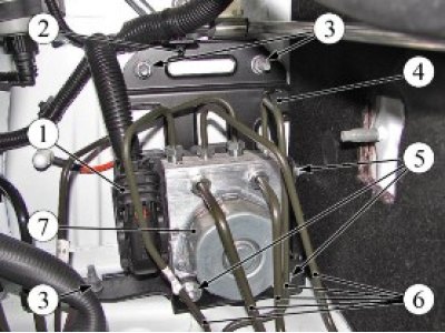
Figure 16-1 - Removing the ABS hydraulic unit: 1 - front wiring harness connector; 2 - Front wiring harness fastening clamp on hydraulic unit bracket; 3 - hydraulic unit bracket mounting nut; 4 - hydraulic unit mounting bracket; 5 - nut for fastening the hydraulic unit to the bracket; 6 - brake pipe; 7 - ABS hydraulic unit
Disconnect brake pipes 6 from the ABS hydraulic unit. Install plugs in the holes of the hydraulic unit and on the brake pipes (key for brake pipes type 41 08 11 13 from "Stahlwille", technological plugs).
Disconnect the clamp 2 of the wiring harness from the bracket 4 of the hydraulic unit mount (pliers).
Remove brake pipes 6 from the mounting brackets on the body (flat head screwdriver).
Unscrew nut 3 and two bolts securing the hydraulic unit bracket to the body and remove the hydraulic unit 7 together with the mounting bracket 4 (replaceable head 13, ratchet wrench).
Unscrew the three nuts 5 securing the hydraulic unit to the mounting bracket and remove the hydraulic unit from the bracket (replacement head 10, ratchet wrench).
Installation
Attention! When replacing the hydraulic unit, perform the procedure for programming the ABS ECU parameters in accordance with the requirements of TI 3100.25100.12054.
Install hydraulic unit 7 on bracket 4 and secure with three nuts 5. Tightening torque of nuts 7...9 N·m (0.7...0.9 kgf·m) (replacement head 10, ratchet wrench, torque wrench).
Install the hydraulic unit assembly with the bracket on the vehicle and secure with nut 3 and two bolts. Tightening torque of nuts 18...24 Nm (1.8...2.4 kgf·m) (replaceable head 13, ratchet wrench, torque wrench).
Connect the plug connector 1 of the front wiring harness to the hydraulic unit connector.
Secure the clamp 2 of the wire harness to the bracket 4 of the hydraulic unit.
Secure the brake pipes 6 to the mounting brackets on the body.
Remove the technological plugs from the openings of the hydraulic unit and brake pipes and connect the brake pipes to the hydraulic unit. Tightening torque of brake pipe fittings 14...20 N·m (1.4...2.0 kgf·m) (brake pipe wrench type 41 08 11 13 from "Stahlwille", replaceable insert 13, torque wrench type 50 18 00 04 of the company "Stahlwille").
Install the soundproofing trim in the engine compartment and secure with eight clips.
Connect the ground wire terminal to the battery (spanner 10).
Bleed the brake system in accordance with the requirements of TI 3100.25100.08020.
Check the efficiency of the service brake system in accordance with the requirements of TI 3100.25100.13062.
Present the vehicle to the Quality Control Department. The Quality Control Department will check the vehicle for compliance with the requirements of TU 017200-254-00232934, paragraphs 1.19.9, 1.19.21, 1.19.22 in the scope of work performed.