
Note. See part numbers for parts. here.
The ABS block is located in the engine compartment and is mounted on the right side member, near the front panel (see fig.2, pos.4 here).
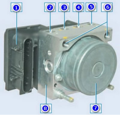
ABS block: 1 - control unit; 2 – a nest of the right forward brake tube; 3 – a nest of a back left brake tube; 4 – a nest of a back right brake pipe; 5 – a nest of a forward left brake tube; 6 – a nest of a tube of the main brake cylinder; 7 - pump; 8 - hydraulic block (hydraulic unit)
Removing
Place the vehicle on a two-post lift, apply the parking brake and turn off the ignition. Open the hood and disconnect the wire terminal "masses" from the battery.
Unscrew the three nuts securing the soundproofing to the front panel and the right mudguard and move the soundproofing to gain access to the hydraulic unit (flat screwdriver).
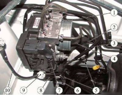
Figure 21-1 - Removing the ABS hydraulic unit: 1 - hydraulic unit (block) ABS; 2 - bracket for fastening the front wiring harness on the valve body bracket; 3 - brake tube; 4 - front wiring harness; 5 - bolts for fastening the valve body bracket; 6 - bracket for fastening the brake pipe on the valve body bracket; 7 - plug block of the front wiring harness; 8 - valve body mounting bracket; 9 - wire fastening bracket "masses" on the bracket of the hydraulic unit; 10 - wire "masses"
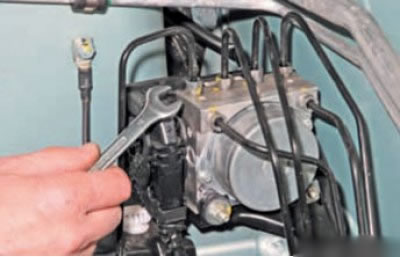
Unscrew the fittings and disconnect the brake pipes from the hydraulic unit of the anti-lock brake system. (key "at 11", or wrench for brake pipes type 41 08 11 13 f. "Stahlwille").
Install plugs in the openings of the hydraulic unit and on the brake pipes.
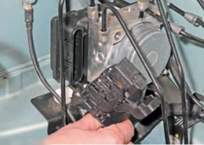
Raising the latch...
... disconnect plug 7, Figure 21-1, of the front wiring harness from the hydraulic unit.
Remove ground wire 10 from bracket 9 (pic. 21-1).
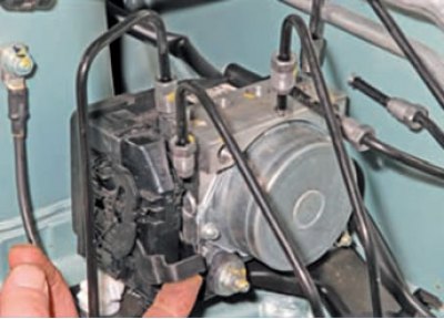
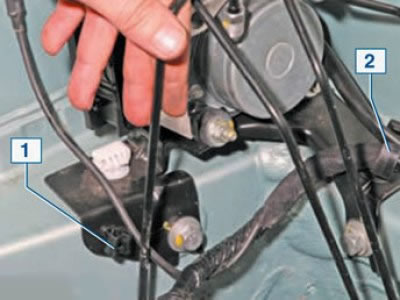
Remove the front wiring harness from bracket 2 (pic. below).
Remove the brake pipe from the fastening bracket 1 to the bracket of the hydraulic unit (pic. below).
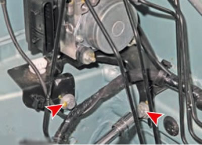
Loosen the bolts securing the hydraulic unit bracket to the body and remove the hydraulic unit (ABS valve body) complete with bracket (interchangeable head 13, ratchet wrench).
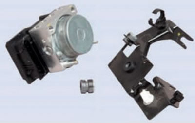
Loosen the bolts securing the hydraulic unit to the mounting bracket and remove the hydraulic unit (interchangeable head 10, ratchet wrench).
Installation
Attention. When replacing the hydraulic unit, perform the ABS computer programming procedure.
Attention. To ensure the tightness of the connector of the control unit of the hydraulic unit, the wire terminal "masses " the hydraulic unit must be oriented downwards.
Install the hydraulic unit on the mounting bracket and secure with bolts. Bolt tightening torque 8 Nm (0.8 kgf·m) (interchangeable head 10, ratchet wrench, torque wrench).
Install the hydraulic unit assembly with the bracket on the vehicle and secure with bolts. Bolt tightening torque 22 Nm (2.2 kgf·m) (interchangeable head 13, ratchet wrench, torque wrench).
Connect the connector of the front wiring harness to the connector of the hydraulic unit.
Install wiring harness, wire "masses" and the brake pipe into the fastening brackets on the bracket of the hydraulic unit (flat screwdriver).
Remove technological plugs from the openings of the hydraulic unit and brake pipes and connect the brake pipes to the hydraulic unit. Tightening torque of fittings 14 Nm (1.4 kgf·m) (wrench for brake pipes type 41 08 11 13 f. "Stahlwille", interchangeable insert 11 type 58 23 10 11 f. "Stahlwille", torque wrench type 50 18 00 04 f. "Stahlwille").
Connect wire terminal "masses" to the battery.
Bleed the brake system (see here).
Check the effectiveness of the working brake system by test drive or on the stand.