



Troubleshooting
The work must be carried out in accordance with the requirements of the labor protection instructions for fitters in force at the enterprise.
The anti-lock braking system (ABS) is part of the vehicle's service braking system and is designed to automatically regulate the degree of wheel slippage in the direction of their rotation during braking by changing the brake fluid pressure in the working brake cylinders in order to prevent loss of control and stability of the vehicle and improve braking efficiency.
ABS also performs the functions of distributing braking forces along the vehicle axles and distributing braking forces along the sides of the vehicle when braking in a turn.
In the variant version, the cars are equipped with an electronic stability control system (ESC), which, in any road conditions, when the car deviates from the set trajectory of movement, automatically brakes one or more wheels and, if necessary, reduces the engine torque, thereby compensating for the deviation and maintaining the stability and controllability of the car.
The ECU system also performs the functions of the ABS.
The anti-lock braking system ABS 9.1 includes:
- hydraulic unit (HA) ABS;
- two wheel speed sensors (WSS) front;
- two wheel speed sensors (WSS) rear;
- two front wheel rotors;
- two rear wheel rotors.
The ABS electrical connection diagram is shown in Figure 1.
The electronic stability control system includes:
- hydraulic unit (HA) ECU;
- two wheel speed sensors (WSS) front;
- two wheel speed sensors (WSS) rear;
- two front wheel rotors;
- two rear wheel rotors;
- steering wheel angle sensor as part of a connector with a rotating device;
- electronic stability control switch.
The electrical connection diagram of the ECU system is shown in Figure 2.
On vehicles with ABS 9.1 and ECU, a data exchange interface via the CAN bus is implemented between the electronic control unit (ECU) of the ABS/ECU hydraulic unit and other vehicle devices (ECU controller, instrument cluster, diagnostic socket, etc.).
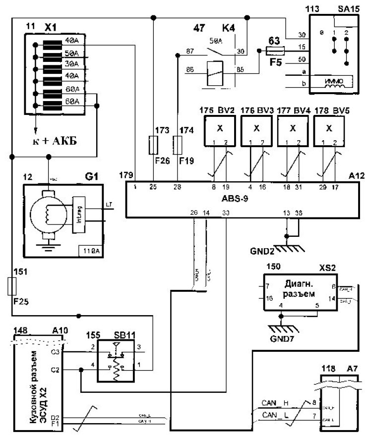
Figure 1 - ABS 9.1 electrical connections diagram: 11 - main fuse box; 47 - additional relay; 113 - ignition switch; 148 - ECU controller; 151 - 10A fuse (F25); 173 - 25A fuse (F26); 175 - Front left DSC; 177 - Rear left DSC; 179 - ECU HA ABS 12 - generator; 63 - fuse 7.5 A (F5); 118 - Instrument cluster; 150 - diagnostic socket; 155 - Brake light switch; 174 - 10A fuse (F19); 176 - Front right DSC; 178 - Rear right DSC;
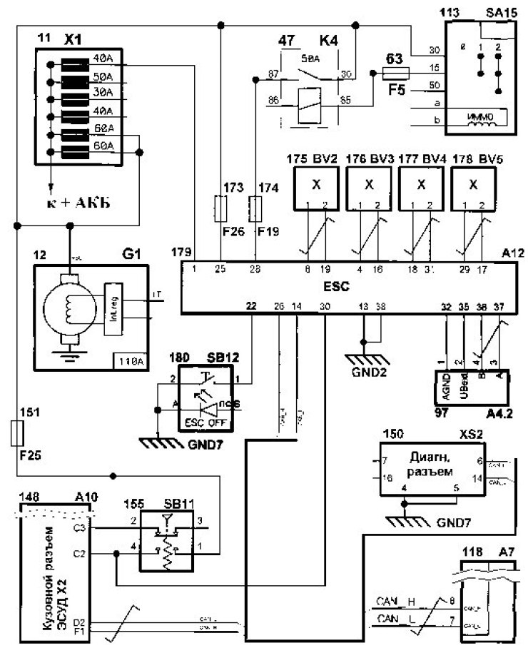
Figure 2 - ECU electrical connection diagram: 11 - main fuse box; 12 - generator; 47 - additional relay; 63 - fuse 7.5 A (F5); 97 - steering wheel angle sensor; 113 - ignition switch; 118 - Instrument cluster; 148 - ECU controller; 150 - diagnostic socket; 151 - 10A fuse (F25); 155 - Brake light switch; 173 - 25A fuse (F26); 174 - fuse 7.5 A (F19); 175 - Front left DSC; 176 - Front right DSC; 177 - Rear left DSC; 178 - Rear right DSC; 179 - - ECU GA EKU 180 - switch of the course stability system
The ABS hydraulic unit (HU) structurally consists of an electronic control unit (ECU) and a hydraulic modulator containing electromagnetic valves (EMV), a return pump and a return pump electric motor (RPM).
The GA ECU also includes an ECU pressure sensor, a lateral acceleration sensor, a longitudinal acceleration sensor, an angular acceleration sensor, and an inertial acceleration sensor.
Wheel speed sensors (WSS) generate signals about the speed of each wheel of the vehicle, which are transmitted to the electronic control unit of the hydraulic unit. The electronic control unit performs logical processing of signals about the wheel speed and, depending on their condition, (excessive acceleration or deceleration of the wheel) sends control commands to the hydraulic modulator. The hydraulic modulator, based on the received commands, turns on or off the electromagnetic valves, reducing, increasing or maintaining constant the pressure of the brake fluid in the wheel brake cylinders, thereby ensuring optimal regulation of the braking forces. When the pressure drops, excess brake fluid is pumped by the return pump into the master brake cylinder.
The purpose of the contacts of the ABS and ECU GA connectors is given in Tables 1-2.
Table 1 - Purpose of ABS GA connector contacts
Contact | Chain |
1 | To terminal "30" (Power supply voltage of the hydraulic unit EWN) |
4 | Front right DSC signal input |
8 | Front left DSC signal input |
13 | "Weight" (Common power supply wire of the hydraulic unit's EWH) |
14 | Input/output. Bus CAN (L - line) |
16 | Front right DSC supply voltage output |
17 | Output of supply voltage of rear right DSC |
18 | Rear left DSC signal input |
19 | Front left DSC supply voltage output |
25 | To terminal "30" (Power supply voltage of the hydraulic unit EMC) |
26 | Input/output. Bus CAN (H - line) |
28 | To terminal "15" (Power supply voltage of the hydraulic unit ECU) |
29 | Rear right DSC signal input |
30 | Input from brake light switch |
31 | Output of supply voltage of rear left DSC |
38 | "Weight" (Common power supply wire for the EMC and the hydraulic unit ECU) |
Table 2 - Purpose of the contacts of the ECU GA connector
Contact | Chain |
1 | To terminal "30" (Power supply voltage of the hydraulic unit EWN) |
4 | Front right DSC signal input |
8 | Front left DSC signal input |
13 | "Weight" (Common power supply wire of the hydraulic unit's EWH) |
14 | Input/output. Bus CAN (L - line) |
16 | Front right DSC supply voltage output |
17 | Output of supply voltage of rear right DSC |
18 | Rear left DSC signal input |
19 | Front left DSC supply voltage output |
22 | Input from the electronic stability control switch ESC |
25 | To terminal "30" (Power supply voltage of the hydraulic unit EMC) |
26 | Input/output. Bus CAN (H - line) |
28 | To terminal "15" (Power supply voltage of the hydraulic unit ECU) |
29 | Rear right DSC signal input |
30 | Input from brake light switch |
31 | Output of supply voltage of rear left DSC |
32 | Output to common wire of steering wheel angle sensor |
35 | Steering wheel angle sensor supply voltage output |
36 | Entrance SASB from the steering wheel angle sensor |
37 | Entrance SASA from the steering wheel angle sensor |
38 | "Weight" (Common power supply wire for the EMC and the hydraulic unit ECU) |
The ABS status is monitored by fault indicators located in the instrument cluster: ABS indicator (orange SE symbol) and an electronic brake force distribution diagnostic indicator (cD symbol red).
The ECU status is monitored by malfunction indicators located in the instrument cluster: ABS indicator (orange color symbol), electronic brake force distribution diagnostic indicator (cD symbol red), ECU alarm (eSC symbol orange), ECU shutdown indicator (orange ESC OFF symbol).
When the ignition is turned on, the ECU switches to the ABS/ECU self-diagnosis mode for about 2 s. At the same time, all the alarms are switched on. After passing the self-diagnosis, if there are no faults in the system, the fault indicators should turn off.
In the presence or occurrence of (during vehicle operation) in case of a malfunction in the ABS/ECU system, the electronic control unit of the hydraulic unit turns on the corresponding diagnostic indicator.
The alarms are controlled via the CAN bus.
Error codes and parameters for performing ABS diagnostics are given in table 3, ECU - in table 4.