



Removal
Place the vehicle on the work post, apply the parking brake and turn off the ignition.
Open the hood and disconnect the wires from the battery (spanner 10).
Loosen the battery clamp bar mounting bolt, remove the bar and battery (replaceable 13 head or T40 Torx head, ratchet, extension).
Remove the air filter from the vehicle in accordance with the requirements of TI 3100.25100.20592 "LADA XRAY vehicle engine - removal/installation of main systems, units and parts".
Disconnect connector 1, Figure 3-1a, of the front left wiring harness from the brake fluid level sensor.
Pump out the brake fluid from reservoir 2, disconnect hose 3 of the clutch master cylinder from the reservoir nipple and install plugs in the hose hole and on the reservoir nipple (brush pump, technological container, flat screwdriver, technological plugs).
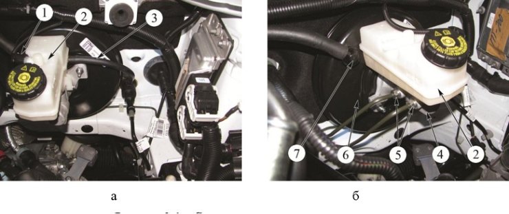
Figure 3-1 - Removing the brake booster: 1 - front left wiring harness connector; 2 - tank; 3 - hose to the clutch master cylinder; 4 - brake master cylinder; 5 - Brake pipe fittings; 6 - brake booster; 7 - Brake booster hose nipple
Disconnect the brake pipe fittings 5, Figure 3-1b, from the brake master cylinder 4, move the pipes to the side and install technological plugs in the holes of the master cylinder and on the brake pipes (13 key for brake pipes, technological plugs).
Disconnect fitting 7 of the hose from vacuum booster 6.
Remove the steering shaft covers in accordance with the requirements of TI 3100.25100.
Disconnect connector 1, Fig. 3-2, of the instrument panel wiring harness from the electronic accelerator pedal 4, unscrew the two nuts 3 securing the accelerator pedal bracket and remove bracket 2 with the accelerator pedal assembly (replaceable head 13, extension, ratchet handle).
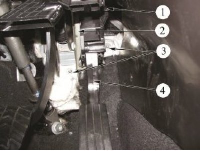
Figure 3-2 - Removing the accelerator pedal bracket: 1 - Instrument cluster harness connector; 2 - accelerator pedal bracket; 3 - accelerator pedal bracket mounting nuts; 4 - electronic accelerator pedal
Disconnect connector 1, Figure 3-3, from the brake light switch.
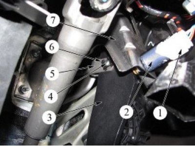
Figure 3-3 - Disconnecting the brake booster rod: 1 - Instrument cluster harness connector; 2 - brake light switch; 3 - brake pedal; 4 - axle connecting fork of brake booster rod and brake pedal; 5 - brake booster rod fork; 6 - axle fixing bracket; 7 - Brake pedal bracket
Turn brake light switch 2 to 0 counterclockwise and remove it from the hole in brake pedal bracket 7.
Disconnect the axle flag from the vacuum booster rod and remove axle 4 from the holes in the fork 5 of the brake booster rod and brake pedal 3.
Unscrew the four nuts 1, Figure 3-4, securing the vacuum booster to the front shield and remove the vacuum booster 3 with the brake master cylinder and reservoir assembly (replaceable head 13, extension, ratchet handle).
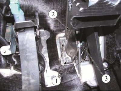
Figure 3-4 - Removing the brake booster: 1 - brake booster mounting nut; 2 - brake pedal bracket; 3 - brake booster
Installation
Install the brake booster on the front shield.
Install bracket 2, Figure 3-4, of the brake pedal onto the studs of the brake booster, screw in and tighten the three nuts 1 securing the brake booster. Tightening torque of fastening nuts 18...24 Nm (1.8...2.4 kgf·m) (replaceable head 13, extension, ratchet handle, torque wrench).
Install bracket 2, Figure 3-2, of the accelerator pedal with pedal 4 in assembly, screw in and tighten the two nuts 3 securing the bracket. Tightening torque of nuts 18.24 N·m (1.8...2.4 kgf·m) (replaceable head 13, extension, ratchet handle, torque wrench).
Install the connecting axle 4, Figure 3-3, into the holes in the fork 5 of the brake booster rod and the brake pedal 3 and fix the axle flag on the vacuum booster rod.
Install the brake light switch into the hole in the brake pedal bracket and turn it clockwise until it stops.
Caution: When installing the brake light switch, do not push or pull the brake pedal.
Connect connector 1, Figure 3-3, of the instrument panel wiring harness to brake light switch 2.
Connect connector 1 of the instrument panel harness to the electronic accelerator pedal.
Apply soap solution to fitting 7, Figure 3-1, of the hose and install the fitting into the hole of the vacuum booster.
Remove the plugs from the brake pipes and the holes of the brake master cylinder, connect the brake pipes to the brake master cylinder 4, Figure 3-1b, and tighten the fittings 5. The tightening torque of the fittings is 15...20 N·m (1.5...2.0 kgf·m) (13 key for brake pipes, replaceable insert 13, torque wrench).
Connect connector 1, Figure 3-1a, of the front left wiring harness to the brake fluid level sensor.
Remove the plugs from the reservoir nipple and the hole in the clutch master cylinder hose, install hose 3, Figure 3-1a, onto reservoir nipple 2.
Install an air filter and resonator on the vehicle in accordance with the requirements of TI 3100.25100.20592 "LADA XRAY vehicle engine - removal/installation of main systems, units and parts".
Connect the wires to the battery (spanner 10).
Fill the reservoir with brake fluid up to the "max" mark on the reservoir body and bleed the brake system in accordance with the requirements of TI 3100.25100.08020.
Bleed the clutch hydraulic drive in accordance with the requirements of TI 3100.25100.20593 "LADA XRAY vehicle transmission - removal/installation of main systems, units and parts".
Check the efficiency of the service brake system in accordance with the requirements of TI 3100.25100.13062.
Present the vehicle to the Quality Control Department. The Quality Control Department will check the vehicle for compliance with the requirements of TU 017200-254-00232934, paragraphs 1.19.9, 1.19.22 in the scope of work performed.