



Removal
Place the vehicle on a two-post lift, apply the parking brake and turn off the ignition (electro-hydraulic lift type P-3.2G with a lifting capacity of 3.2 t).
Remove the front wheel in accordance with the requirements of TI 3100.25100.20594.
Raise the vehicle to a height convenient for performing work.
Clean the front brake parts (metal brush).
Remove the front brake hose in accordance with the requirements of paragraph. 20 real TI.
Unscrew the two bolts 1, Figure 6-1, securing the guide 3 of the front brake to the steering knuckle, remove the bolts and remove the front brake assembly (replacement head 18, extension and ratchet).
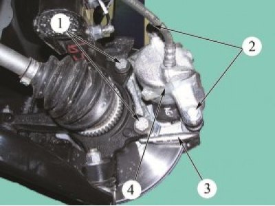
Figure 6-1 - Removing the front brake guide: 1 - guide rail mounting bolts; 2 - guide pin mounting bolts; 3 - front brake guide; 4 - support
Installation
Attention! After removal, bolts 1, Figure 6-1, securing the guide to the steering knuckle must be replaced.
Install the front brake assembly onto the steering knuckle and secure the front brake guide with new mounting bolts. Tightening torque of bolts 90...120 Nm (9.0...12.0 kgf·m) (replaceable head 18, extension, ratchet, torque wrench).
Install the front brake hose in accordance with the requirements of Section 15 of this technical instruction.
Install the front wheel in accordance with the requirements of TI 3100.25100.20594.
Bleed the brake system in accordance with the requirements of TI 3100.25100.08020.
If necessary, bleed the clutch hydraulic drive in accordance with the requirements of TI 3100.25100.20593 "LADA XRAY vehicle transmission - removal/installation of main systems, units and parts".
Check the efficiency of the service brake system in accordance with the requirements of TI 3100.25100.13062.
Present the vehicle to the Quality Control Department. The Quality Control Department will check the vehicle for compliance with the requirements of TU 017200-254-00232934, paragraphs 1.19.9, 1.19.22 in the scope of work performed.