



The pressure regulator in the rear brake hydraulic drive ("sorcerer") is located on the bottom, between the rear suspension beam and the body (see photo).
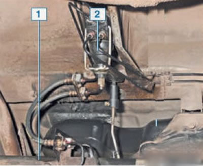
1 — rear suspension beam; 2 - pressure regulator;
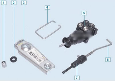
1 – adjusting nut; 2 – plastic sleeve; 3 – push lever; 4 – regulator bracket; 5 – pressure regulator; 6 – regulator rod; 7 – traction control sleeve
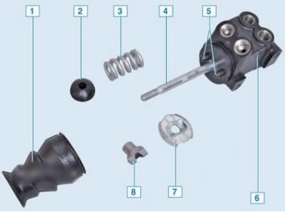
Brake pressure regulator parts: 1 – anther; 2 – support sleeve; 3 – spring; 4 – regulator pin; 5 – regulator pistons; 6 – body; 7 – thrust washer; 8 – guide bushing
Original text is available on the website Ladaman.ru
Removal
Place the vehicle on a four-post lift, apply the parking brake and turn off the ignition (four-post platform lift type P-178D-03 with a lifting capacity of 3.5 tons).
Raise the vehicle to a height convenient for performing work.
Unscrew the fittings of the brake pipes 1 and 2, Figure 16-1, from the rear brake pressure regulator 4 and install plugs on the brake pipes and in the holes of the pressure regulator (brake pipe wrench type 41 08 11 13 f. "Stahlwille", technological plugs).
Disconnect the 5 rod of the rear brake pressure regulator drive from the beam 6 of the rear suspension arms (flat head screwdriver, pliers).
Loosen the 3 pressure regulator mounting bolts and remove the regulator (replacement head 10, extension, ratchet wrench).
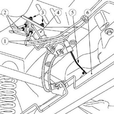
Figure 16-1 - Removing the rear brake pressure regulator: 1 - brake pipes from the brake master cylinder to the pressure regulator; 2 - brake pipes from the pressure regulator to the rear brake wheel cylinders; 3 - rear brake pressure regulator mounting bolts; 4 - rear brake pressure regulator; 5 - pressure regulator drive rod; 6 - rear suspension arm beam
Installation
Install the rear brake pressure regulator in place and secure it with bolts. Tightening torque of bolts 12 Nm (1.2 kgf·m) (replacement head 10, extension, ratchet wrench, torque wrench).
Remove the plugs from the holes in the regulator and brake pipes and screw the fittings of the brake pipes into the holes in the rear brake pressure regulator. Tightening torque of the fittings 14 Nm (1.4 kgf·m) (brake pipe wrench type 41 08 11 13 f. "Stahlwille", replaceable insert 11 type 58 23 10 11 f. "Stahlwille", torque wrench type 50 18 00 04 f. "Stahlwille").
Connect the rear brake pressure regulator drive rod to the rear suspension beam (flat head screwdriver, pliers).
Bleed the brake system.
Adjusting the rear brake pressure regulator drive.
Attention: When adjusting, the car must be in running order and standing on its wheels.
Adjust the rear brake pressure regulator, for which:
- unscrew the tightening bolt 2, figure 16-2, of the adjusting sleeve;
- install the adjusting sleeve 3 of the drive lever so that it touches the lever 4 of the rear brake pressure regulator;
- tighten the tie bolt. Bolt tightening torque 12 Nm (1.2 kgf·m) (replacement head 10, ratchet wrench, torque wrench).
Attention: When adjusting, do not apply pressure to nut 6 of the regulator rod.
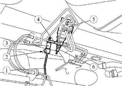
Figure 16-2 - Adjusting the rear brake pressure regulator drive: 1 - pressure regulator drive rod; 2 - tension bolt of the drive rod adjusting coupling; 3 - drive rod adjustment coupling; 4 - rear brake pressure regulator drive lever; 5 - rear brake pressure regulator; 6 - regulator rod nut
Checking the rear brake pressure regulator
Caution: The rear brake pressure regulator must be checked with the vehicle parked on its wheels, with one person on board and a full fuel tank.
The pressure reading is made diagonally by comparing the pressure in the rear brake mechanism with the specified pressure in the front brake mechanism.
If the pressure value on any of the rear brake mechanisms is not within the normal range, replace the rear brake pressure regulator.
Caution: Be sure to check both brake circuits. Right front/left rear wheel and left front/right rear wheel.
Remove the protective caps, unscrew the brake bleed nipples from the right front and left rear brake mechanisms and connect the pressure gauges to them (spanner 7, two pressure gauges type Fre. 1085-01).
Bleed the brake system through the bleed nipples on the pressure gauges.
Start the engine.
Press and hold the brake pedal in a position corresponding to a pressure in the front brake working cylinder of 100 bar.
Record the readings of the pressure gauge connected to the rear brake working cylinder.
Repeat the operation on the other brake circuit.
If the pressure values exceed the permissible values specified in Tables 16-1 and 16-2, the rear brake pressure regulator must be replaced. Regulator repair is not provided.
Attention. The pressure difference in the working cylinders of the rear brakes must not exceed 4 bar, regardless of the load on the rear axle.
Control values of pressure in rear wheel cylinders
Control pressure values are given in Tables 16-1 and 16-2.
Table 16-1 - Without taking into account axle load distribution (pressure check is performed with a full fuel tank)
| Model car | Rear wheel cylinder pressure, bar Modification E0/E1 | Rear wheel cylinder pressure, bar Modification E2 | ||
| Engine K7M | Engine K4M | Engine K7M | Engine K4M | |
| R90 | 37,50...48,40 | 29,50...40,40 | 37,00...47,90 | 28,80...39,90 |
Table 16-2 - Taking into account the distribution of loads on the axles
| Car model | Rear wheel cylinder pressure, bar (with a rear axle load of 700 kg) | Rear wheel cylinder pressure, bar (with a rear axle load of 825 kg | ||
| Engine K7M | Engine K4M | Engine K7M | Engine K4M | |
| F90 | 50,68...61,88 | Measurement is not performed | 64,20...75,40 | Measurement is not performed |
| R90/5 - local | 50,68...61,88 | 42,24...53,44 | 64,20...75,40 | 57,20...68,30 |
| R90/7 - local | 48,92...60,12 | 40,90...52,10 | 59,90...71,10 | 52,40...63,60 |
Bleed the brake system and, if necessary, the clutch hydraulic drive (see here).
Check the efficiency of the service brake system.