
Catalog numbers of rear pads and other elements of the brake mechanism see here.
Caution: Brake pads have slightly uneven lining wear or wear that varies between different pads. The pads can also have significantly different wear on opposite ends of the lining. If everything else is in good condition, these features do not indicate any problems.
Note. It is not recommended to disassemble the rear brake mechanism without special need, to remove the brake drum. Use the inspection holes to check rear pad wear. (see below)
Wear check (thickness) rear pads without removing the brake drum
The rear pad, located closer to the front of the car, wears out faster than the rear. Therefore, to control...
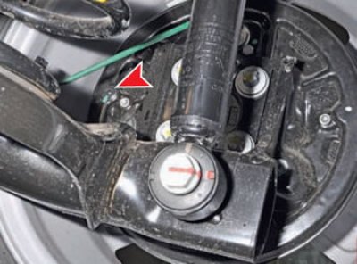
... there is an inspection hole in the rear brake shield.
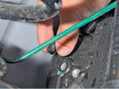
Take out the rubber plug.
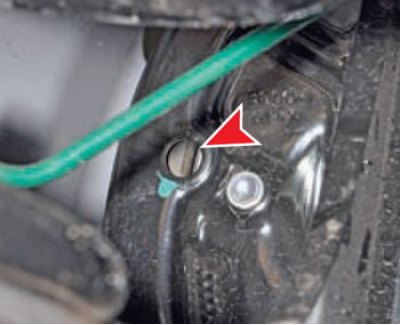
Minimum allowable rear brake pad thickness (overlays) - 1.5 mm.
For better control, you need to remove the brake drum (see below).
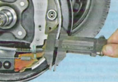
When measuring the thickness together with the base of the overlay, the minimum allowable thickness is 5 mm.
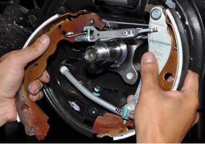
Replacement
The brake should be disassembled first from one wheel. While this job can be done with normal hand tools, there are a few specialized brake repair tools that will make repairs much easier. It is recommended to provide a tool to remove the springs on the brakes.
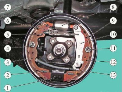
Figure 14-1 - Replacing the brake pads: 1 - emphasis; 2 - lower coupling spring; 3, 12 - brake pads; 4, 11 - guide springs; 5, 9 - springs for fastening the automatic gap adjustment mechanism; 6 - spacer bar with automatic gap adjustment mechanism; 7 - upper coupling spring; 8 - brake cylinder; 10 - lever for manual drive of the pads; 13 - hand brake cable
Removing
Apply the parking brake and turn off the ignition. Jack up the vehicle on one side and install jack stands, or place the vehicle on a two-post lift.
Remove the rear wheel.
Release the hand brake lever.
If you are working on a lift, raise the vehicle to a height that is comfortable for the work to be done.
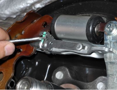
To facilitate the removal of the brake drum, you need to bring the brake pads together. To do this, use a flat screwdriver through the hole in the brake drum to rotate the gear nut of the gap adjustment mechanism between the pads and the drum, due to which the length of the spacer bar is reduced and the pads converge. The direction of rotation is from top to bottom.
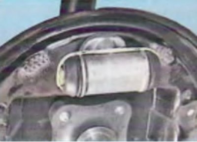
What it looks like with the drum removed:
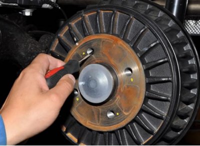
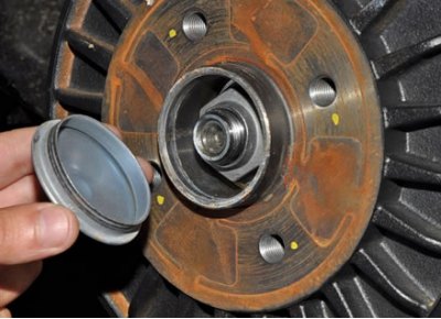
Using suitable tools, pry and knock out the wheel bearing cap.
And take it off.
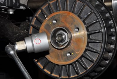
key (head) "at 36" unscrew the hub nut.
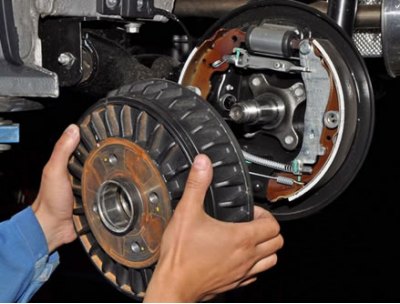
And remove the brake drum.
Note. It is forbidden to press the brake pedal after removing the brake drum.
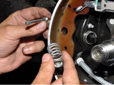
Remove springs 4 and 11 of guide shoes (pliers). For this:
Using pliers, turn the spring cup until the groove in the cup aligns with the shank of the rack.
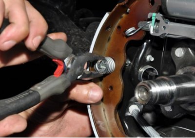
Then remove the spring with the cup, and also remove the support post (guide).
Do the same on the other side of the mechanism.
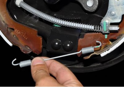
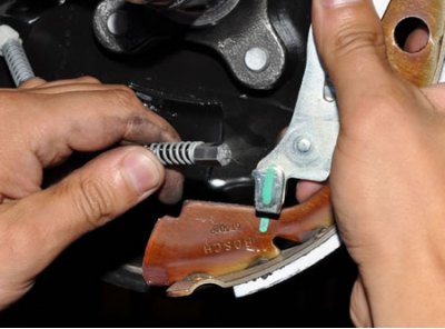
Remove lower return spring 2 (figure 14-1).
To do this, hook its hook with a suitable tool and disengage it.
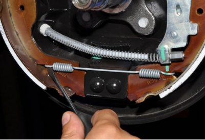
Remove the spring completely.
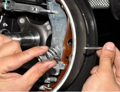
Holding the pads with your hands, carefully remove them from the shield together with the adjusting mechanism.
And disconnecting the tip of the handbrake cable (13, fig. 14-1), completely remove the pads from the shield.
After removing the pads, it is advisable to somehow fix the pistons of the working cylinder, for example, tie them with wire or rope. This is necessary in case the pistons squeeze out and brake fluid can leak out.
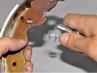
Remove the top return spring from the shoe assembly (7, Fig.14-1).
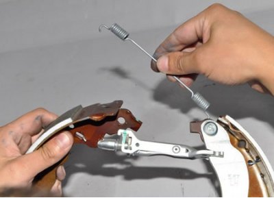
Disconnecting the adjuster spring from the front shoe...
And removing the spacer bar from the rear shoe...
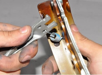
Remove the spacer bar with the automatic adjustment mechanism assembly.
The mechanism for automatic adjustment of the gap between the shoes and the drum:
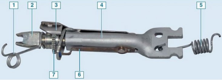
1 - threaded tip spring; 2 - threaded tip of the spacer bar (left hand thread); 3 - spring lever of the regulator; 4 - spacer bar; 5 - leaf spring; 7 - ratchet gear nut (left hand thread)
General view of the elements of the rear brake mechanism in a disassembled state
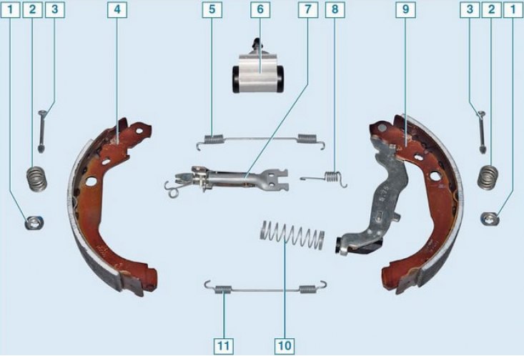
Elements of the brake mechanism: 1 - spring cup; 2 - clamping spring pads; 3 - support post; 4 - front block; 5 - upper coupling spring; 6 - wheel cylinder; 7 - spacer bar; 8 - regulator spring; 9 - rear shoe with parking brake lever; 10 - lower coupling spring
Installation
Clean rear brake elements (metal brush).
Apply lubricant to the threaded surface of the spacer bar "Litol 24".
Before installing the pads on the brake shield, connect the pads to each other with a spacer bar with an automatic gap adjustment mechanism and fastening springs, connect the manual brake cable to the drive lever (flathead screwdriver, pliers).
Install the pads on the brake shield.
Install upper and lower return springs (brake spring pliers).
Install guide pad springs (flathead screwdriver, pliers).
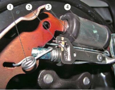
Figure 14-2 - Elements of the rear brake: 1 - spring for fastening the spacer bar; 2 - ratchet mechanism for automatic clearance adjustment; 3 - spacer bar with automatic gap adjustment mechanism; 4 - upper coupling spring
Adjust the outer diameter of the pads by turning the ratchet 2, Figure 14-2, of the automatic gap adjustment mechanism with a screwdriver. Outer diameter of pads must be 227.5±0.1 mm (flathead screwdriver, caliper).
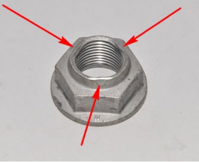
Install the brake drum. Tightening torque of the hub bearing nut 175 N∙m.
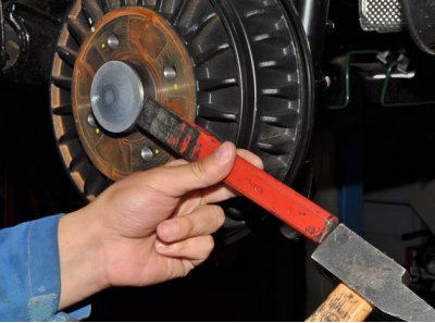
It is advisable to use a new nut (nut article: 7703034275), but you can also use the restored old one by crushing its shoulder in three places with a hammer, as shown in the photo:
Install the rear wheel.
Press the brake pedal 2-3 times, check and, if necessary, top up the level of brake fluid in the reservoir of the hydraulic brake drive.
Check the operation of the mechanism for automatically adjusting the gap between the shoes and the drum (when you press the brake pedal several times in a row, a characteristic click should be heard).
Adjust parking brake.
Check the efficiency of the service brake system.