



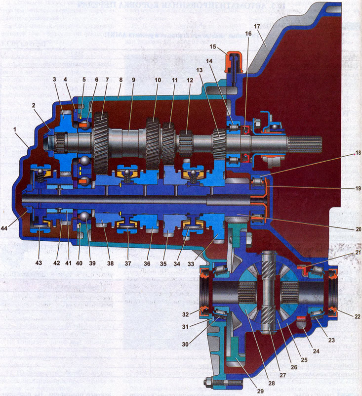
Transmission: 1 - rear cover of the gearbox housing; 2, 44 - nut; 3 - fifth gear leading pinion; 4 - thrust plate; 5, 40 - bearing retaining rings; 6 - primary shaft ball bearing; 7 - fourth gear leading pinion; 8 - gearbox housing; 9 - primary shaft; 10 - third gear leading pinion; 11 - second gear leading pinion; 12 - reverse gear; 13 - first gear drive pinion; 14 - roller bearing; 15 - breather; 16 - primary shaft seal; 17 - clutch housing; 18 - secondary shaft roller bearing; 19 - oil collector; 20 - main gear drive pinion; 21 - Vehicle speed sensor ring; 22, 32 - drive seals; 23, 30 - tapered roller bearings of the differential; 24 - vehicle speed sensor; 25 - differential box; 26 - differential satellite; 27 - satellite axis; 28 - axle gear; 29 - driven gear of the main transmission; 31 - adjusting ring; 33 - driven gear of the first gear; 34 - synchronizer of the first and second gears; 35 - driven gear of the second gear; 36 - driven gear of the third gear; 37 - synchronizer of third and fourth gears; 38 - driven gear of the fourth gear; 39 - secondary shaft ball bearing; 41 - bushing; 42 - driven gear of fifth gear; 43 - fifth gear synchronizer
In a car with a manual transmission (MT), the driver selects the moment of gear shifting and the shifting itself. Despite the obvious disadvantage of such a design - you have to constantly work the clutch pedal - there are also positive aspects: lower price, simple design, high reliability and economy in comparison with a hydromechanical unit - an automatic transmission of a "classic" design. The idea of combining the advantages of a manual transmission with the convenience of controlling an automatic gearbox is realized in an automated manual transmission (AMKP). This type of gearbox is often called robotic.
It enables gear shifting without driver intervention depending on vehicle speed, engine speed and load. The driver only needs to select the gearbox operating mode by moving the automatic transmission mode selector to the appropriate position. The selector cover is marked with the lever position.
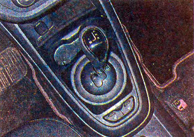
For an experienced driver, there is an opportunity to control the transmission operation in manual mode, based on his driving style, and not to adjust to a given algorithm embedded in the "electronic brain". The automatic transmission, which is installed on Lada cars, is a "regular" mechanical box with an electronically controlled gear shift mechanism and an electric clutch release drive.
The automated gearbox was developed jointly with the German company ZF based on the five-speed manual transmission model 2180.
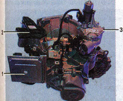
Automated manual transmission model 2182: 1 - electronic transmission control unit; 2 - Electric clutch release drive; 3 - Electric gear shift mechanism
The upgraded unit received the designation 2182. Instead of a gear shift mechanism with a cable drive (which was on the MKP 2180) an electric drive mechanism was installed on it.
The electric clutch release drive acts directly on the clutch fork.
There is no clutch pedal on the car.
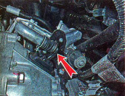
Note: The parts listed are removable, but the gearbox housing remains unchanged. This allows, if necessary, to convert the unit to manual control. To do this, you will need to install a cable-operated gear shift mechanism and a clutch release cable.
The gearbox is two-shaft. It is mounted together with the main transmission and differential into a single unit, the body of which consists of three parts - the clutch housing, the gearbox housing and the rear cover. The joints between the crankcases and the cover are sealed with a petrol-oil-resistant sealant.
The primary shaft of the gearbox is made in the form of a block of gears. The primary shaft gears are driving gears and are in constant engagement with the driven gears of the forward gears mounted on the secondary shaft. All elements of the secondary shaft are removable. The secondary shaft is hollow, with radial holes in the places where the gears are installed for lubrication of the outer surface of the shaft. The fifth gear pinion rotates on the sleeve.
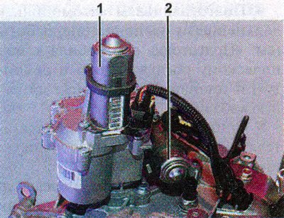
Electric gear shift mechanism: 1 - electric gear selection drive; 2 - electric gear shift drive
The main gear drive pinion and synchronizer hubs are mounted on the shaft splines. The most loaded synchronizers (first and second gears) have two additional conical rings.
The front ends of the shafts are supported by roller bearings, and the rear ends by ball bearings.
The differential is a two-satellite one, the preload of its bearings is adjusted by selecting the thickness of the adjusting ring installed under the outer ring of the differential bearing. A vehicle speed sensor setting ring is installed on the differential housing. The sensor is installed on the gearbox housing.
To control the oil level in the gearbox housing, a special hole is made, closed with a threaded plug.