



Open large image in new tab »
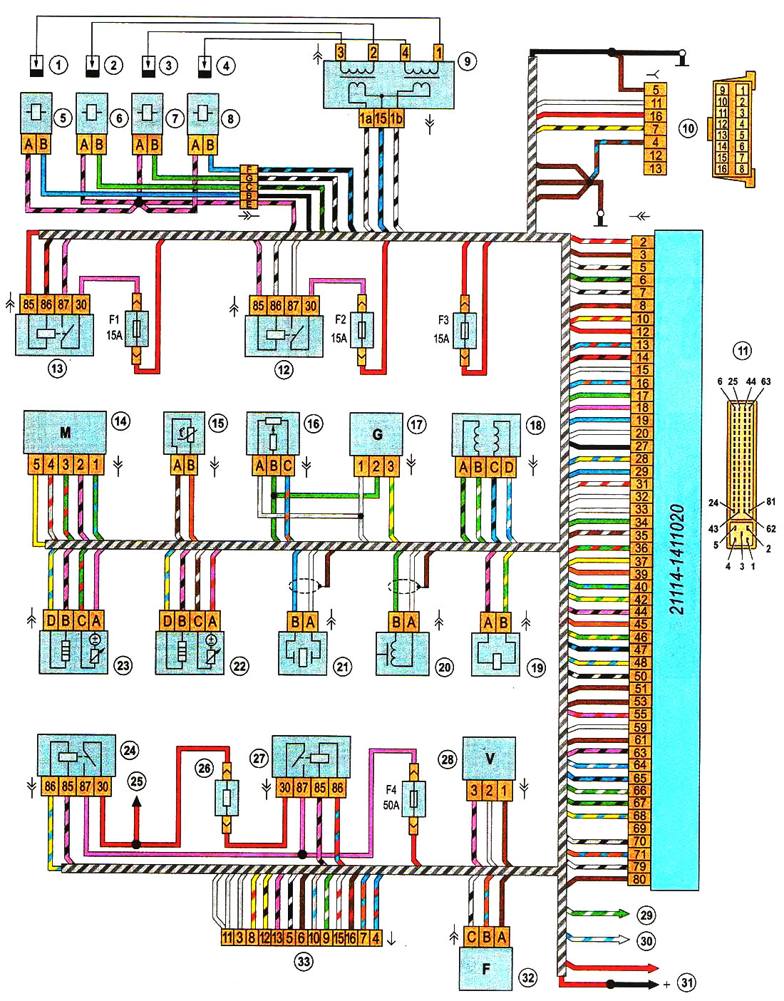
1.6i engine management system diagram (EURO III): 1 - spark plug of the first cylinder; 2 - spark plug of the second cylinder; 3 - spark plug of the third cylinder; 4 - spark plug of the fourth cylinder; 5 - nozzle of the first cylinder; 6 - nozzle of the second cylinder; 7 - nozzle of the third cylinder; 8 - nozzle of the fourth cylinder; 9 - ignition coil; 10 - block diagnostic connector; 11 - electronic control unit (ECU); 12 - relay for turning on the fuel pump; 13 - main relay of the engine management system; 14 - mass air flow sensor; 15 - coolant temperature sensor; 16 - throttle position sensor; 17 - rough road sensor; 18 - idle speed regulator; 19 - adsorber purge valve; 20 - crankshaft position sensor; 21 - knock sensor; 22, 23 - oxygen concentration sensors; 24 - relay for turning on the electric fan of the engine cooling system (high speed); 25 - to the electric fan of the engine cooling system; 26 - additional resistor of the electric fan of the engine cooling system; 27 - relay for turning on the electric fan of the engine cooling system (low speed); 28— vehicle speed sensor; 29 - to the coolant temperature indicator sensor; 30 - to the emergency oil pressure sensor in the engine; 31 - to the positive terminal of the battery; 32 - camshaft position sensor; 33 - block for connection to the electrical network of the car; F1 - fuse for the computer and circuits of the engine management system; F2 - fuel pump circuit fuse; F3 - ECU fuse; F4 - fuse for the electric fan of the engine cooling system
Note. The connection to the fuel pump is made through the electrical network of the vehicle (see «Scheme of electrical equipment of a car with a sedan body» or «Scheme of electrical equipment of cars with hatchback and station wagon bodies»).
Note. The connection to the fuel pump is made through the electrical network of the vehicle (see «Scheme of electrical equipment of a car with a sedan body» or «Scheme of electrical equipment of cars with hatchback and station wagon bodies»).