



The location of the air flow distribution organs is shown in the figure 1.8, the location of the heating and ventilation controls is shown in Figure 1.9.
The following air flow distribution elements are located on the instrument panel.
1 - air ducts supplying air to the feet of passengers in the rear seat.
2 - side air nozzles for supplying air to the driver and front seat passenger or to the front door windows. The direction of the air flow is adjusted by turning the grille (in the vertical direction) and sashes (in the horizontal direction) by the handle in the middle of the grate. The intensity of the air flow is regulated by moving the handle under the nozzle horizontally. At the left nozzle, when the handle is in the extreme left position, the air flow is blocked; at the right nozzle, the flow is maximum. The algorithm for controlling the flow intensity from the right nozzle is symmetrical.
3 - nozzles for blowing air into the front door windows.
4 - windshield blower nozzles.
5 - upper nozzle for supplying air to the passenger compartment.
6 - central nozzles for supplying air to the passenger compartment. The direction of the air flows from the central nozzles is adjusted in the same way as from the side nozzles 2. The intensity of the air flows is adjusted by moving the handle between the nozzles in the vertical direction. In the extreme lower position of the handle, the air flow is blocked; in the upper position, air is supplied through nozzle 5. In the intermediate position of the handle, air is supplied through both the upper and central nozzles;
7 - central nozzle position control handle.
Interior ventilation
To ventilate the passenger compartment, set the ventilation and heating control unit controls to the following positions.
Article copied from the resource www.LadaMan.ru
1. Turn the regulator knob 1 clockwise until it stops (see figure 1.9) supply air temperature.
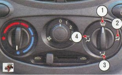
2. Set the control knob 3 opposite the pictogram 2 (see photo) (see figure 1.9) distribution of air flows.
3. Open nozzles 2 and 6 (see figure 1.8), turning the handle between the central nozzles down, the handle under the left side nozzle to the right, and under the right side nozzle to the left.
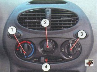
Figure 1.9. Interior heating and ventilation control knobs: 1 - supply air temperature regulator; 2 - heater fan mode switch; 3 - air flow distribution regulator; 4 - outside air supply regulator
4. Set the desired air flow rate using switch 2 (see figure 1.9) operating modes of the heater electric fan.
5. If the windshield fogs up, set the control knob 3 opposite the icon 1 (see photo).
Preventing fogging of glass
At high air humidity (during heavy rain) the windows of the Lada Kalina car may fog up. To prevent the windshield and front door windows from fogging up, do the following.
1. Turn the regulator knob 1 counterclockwise until it stops (see figure 1.9).
2. Set the control knob 3 opposite the icon 1.
3. Set the heater electric fan mode switch 2 to position "2".
Cleaning glass from snow and ice
To quickly clear snow and ice from your windshield and front door windows, follow these steps:.
1. Turn the regulator knob 1 counterclockwise until it stops (see figure 1.9).
2. Set the control knob 3 opposite the icon 1.
3. Set the heater electric fan mode switch 2 to maximum speed.
Quick warm-up of the interior
To quickly warm up the air in the cabin, do the following.
1. Turn the regulator knob 1 counterclockwise until it stops (see figure 1.9).
2. Set the control knob 3 opposite the icon 2.
3. Set the heater electric fan mode switch 2 to position "3".
4. Open the side 2 and central 6 nozzles (see figure 1.8).
5. Set the control knob 4 to the extreme right position - outside air does not enter the passenger compartment (recirculation mode).
Ensuring a comfortable air temperature in the cabin
If the windows in the Lada Kalina car are clean, but the temperature has not reached the desired level, do the following.
1. Set the desired temperature using the regulator 1 (see figure 1.9).
2. Set the control knob 3 opposite the icon 3.
3. Select the required intensity of warm air supply to the passenger compartment using switch 2 of the heater fan operating modes.
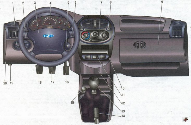
Figure 1.6. Instrument panel and controls Lada Kalina VAZ 1118
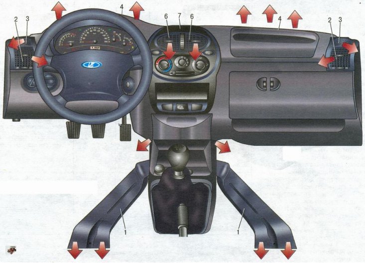
Figure 1.8. Air flow distribution organs Lada Kalina VAZ 1118