
Comment. Removal of the gear shift actuator may be required when replacing defective parts (e.g. to replace a torn drive rod boot).
To perform the work, you will need an assistant, as well as a viewing ditch or overpass.
Removal assembly
1. We prepare the car for work («Preparing the car for maintenance and repair»).
2. We clean the threads of the coupling bolt of the clamp with a metal brush. We process the junction of the rod with the hinge and the bolt with a penetrating lubricant.
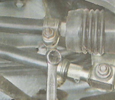
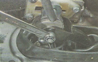
3. With a 13 mm wrench, we loosen the tightening of the nut of the clamp coupling bolt.
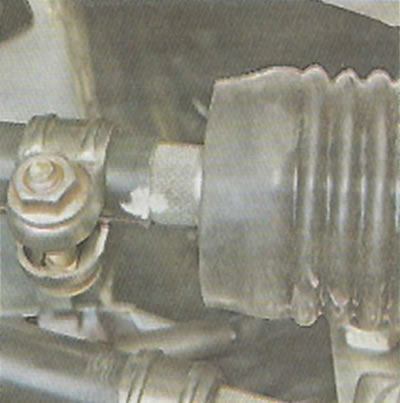
4. Unclench the clamp with a screwdriver and move it along the rod. We unclench the thrust with a screwdriver.
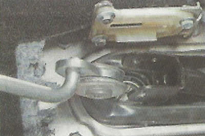
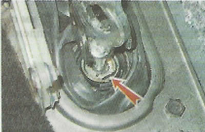
5. After wiping the junction of the rod with the hinge with a rag, we mark the relative position of the drive rod and the hinge.
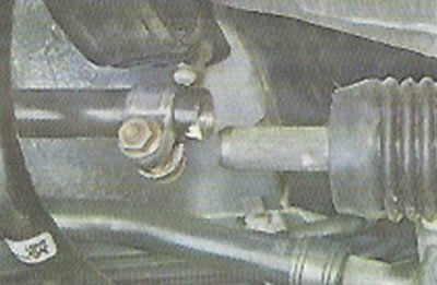
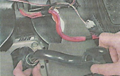
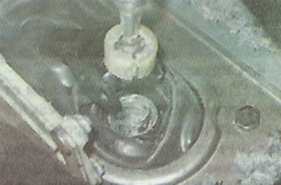
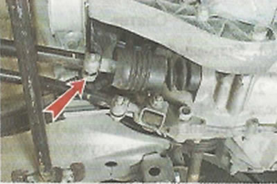
6. Disconnect the rod from the hinge.
7. Disconnect the jet thrust from the base of the ball joint of the gear lever («Jet thrust - removal and installation»).
8. In the car, remove the lining of the floor tunnel («Floor tunnel lining - removal and installation»).
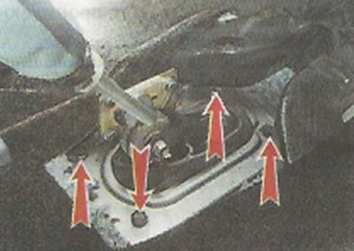
9. Using a 13 mm wrench, unscrew the four bolts securing the gear lever support to the body.
10. Remove the drive down, bringing the gear lever through the hole in the floor tunnel.
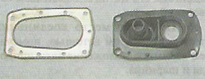
11. To replace the cover, unscrew the limiter fastening nut and remove the rod (see below).
12. Remove the bracket and cover drive rod. We replace the torn cover.
13. Install the drive in reverse order.
Drive rod replacement
Comment. To replace some parts (e.g. thrust) you can partially disassemble the drive, but remove it from the car. It may be necessary to replace the drive link if it is deformed and if the link cannot be securely connected to the pivot on the gearbox due to corrosion or other damage.
1. Disconnect the drive rod from the gearbox (see above) and remove the steel clamp from the rod.
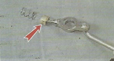
2. Using a 13 mm wrench, unscrew the limiter fastening nut.
3. Remove the limiter from the lever.
4. We remove the lever from the thrust fork.
5. To remove the drive rod, lubricate it with soapy water and remove it from the opening of the cover.
6. Install the traction in reverse order. Before the final tightening of the clamp of the drive rod of the gear change mechanism, we adjust the drive (see below).
Disassembly of the arm support
Comment. The work can be done by removing the gearshift drive from the vehicle (see above) or by dismantling the support directly on the vehicle.
1. Disconnect the drive rod from the gear lever (see above).
2. Remove the metal...
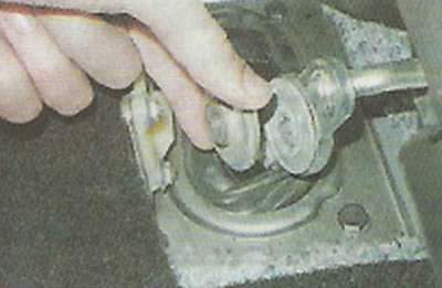
...and plastic washers.
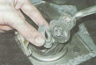
3. We take out the metal spacer.
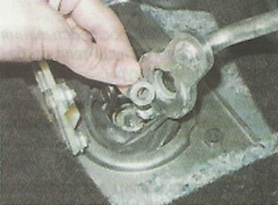
4. Remove the washers on the other side of the lever.
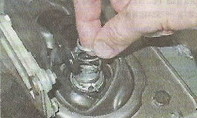
5. Using a slotted screwdriver, pry off and remove the retaining ring of the ball joint of the lever.
6. We take out the lever from the base of the support.
7. We take out the spring from the support.
8. If necessary, remove the support from the lever and replace the damaged parts.
9. We assemble the lever support in the reverse order, lubricating the parts with technical vaseline VTV-1 or other grease. When assembling, we also lubricate the washers and the lever bushing.
Adjustment
Comment. The drive has a device that blocks the erroneous engagement of reverse gear instead of first gear. A special template is required to adjust the drive, but if it is not available, then the drive can be adjusted with the help of an assistant. The gearbox must be in first gear. If the plastic pad on the bracket will prevent the gear from being engaged, it should be removed (unscrewing two nuts and a bolt).
1. Weaken the tightening of the clamp of the drive rod of the gear shift mechanism (see above).
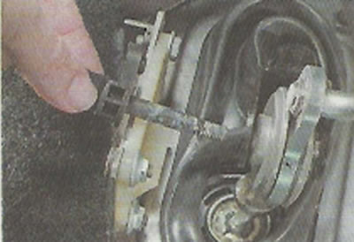
2. We shift the gear lever so that its limiter touches the plastic lining of the bracket A, and then move the lever forward, but so that the limiter does not move beyond the slot of the lining B.
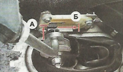
3. Hold the lever in this position. while the assistant tightens the metal clamp of the thrust at a distance of 2-3 mm from the end.
4. Turning on the reverse gear, we make sure that the gear shift mechanism drive is working.
Comment. After pressing the lever from above, its limiter should be opposite the wide part of the slot in the plastic lining of the bracket, and when the lever is moved to the left, the limiter should enter the slot without clinging to its edges. There should be enough freedom of movement of the limiter inside the slot to engage reverse gear. If the limiter clings to the edges of the slot or the limiter rests against the slot at the end of the stroke, and the reverse gear is not yet engaged, it is necessary to repeat the adjustment, slightly changing the position of the rod on the pivot rod.
5. At the end of the adjustment, install the removed parts.