



Removal
Place the vehicle on a two-post lift, apply the parking brake, turn off the ignition, open the hood and disconnect the ground wire from the battery (two-post lift type P3.2G with a lifting capacity of 3.2 t, spanner 10).
Remove the air filter with the intake pipe hose and the air supply pipe assembly in accordance with the requirements of Section 3 of this TI.
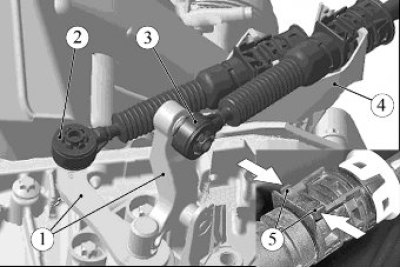
Figure 4-1 - Shift Cables: 1 - gear shift levers; 2 - gear shift cable tip; 3 - gear selection cable tip; 4 - gear shift cable mounting bracket; 5 - retainer antennae
Disconnect the ends 2 and 3, Figure 4-1, of the shift and gear selection cables from the ball heads of the levers 1 of the gear shift mechanism (wedge 67.7812-9707-000, hammer).
Squeeze the tabs 5 of the retainer and remove the gear shift cables from the slots of the mounting bracket 4.
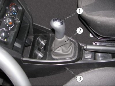
Figure 4-2 - Removing the floor tunnel lining: 1 - gear shift lever handle; 2 - gear shift lever cover; 3 - floor tunnel lining
Detach cover 2, Figure 4-2, from the floor tunnel lining (flat head screwdriver).
Remove handle 1 with cover 2 as an assembly by pulling the handle upwards along the axis of the gear shift lever.
Remove the lining of the 3rd floor tunnel in accordance with the requirements of TI 3100.25100.20599. Remove the noise insulation from the control drive housing.
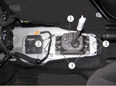
Figure 4-3 - Removing the gearshift control drive: 1 - gear shift control drive; 2 - mounting bolt; 3 - retainer
Unscrew the four bolts 2, Figure 4-3, fastenings, press the two clamps 3 and lower the control drive 1 down onto the heat shield (replacement head 10, extension, ratchet).
Disconnect the additional muffler from the intake pipe in accordance with the requirements of TI 3100.25100.20592.
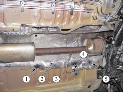
Figure 4-4 - Removing the Front Heat Shield: 1 - nut; 2 - front thermal screen; 3 - oxygen sensor wiring harness; 4 - places for attaching wire harnesses; 5 - Engine wiring harness
Disconnect wire harnesses 3 and 5 from front heat shield 2, Figure 4-4.
Unscrew the eight nuts 1 of the fastening and remove the heat shield 2 (replacement head 24, extension, ratchet).
Remove drive 1, Figure 4-3, gear shift control with cables assembly.
Installation
Install drive 1, Figure 4-3, gear shift control assembly with cables on the vehicle into the floor tunnel opening. Make sure that the control drive is held in the hole by clamps 3.
Tighten four bolts 2 securing the control drive 1. Tightening torque of bolts 7...9 Nm (0.7...0.9 kgf·m) (replaceable head 10, extension, ratchet, torque wrench).
Install noise insulation on the control drive housing.
Install the gearbox control cables into the slots of bracket 4, Figure 4-1, on the gearbox.
Apply grease to the spherical pins of the levers of the gearshift mechanism 1 on the gearbox and connect the ends 2 and 3 of the cables to the levers (AZMOL LSC-15 grease according to the current "Codifier of the main and auxiliary materials used in the maintenance and repair of LADA vehicles" K 3100.25100.00018, consumption rate 1 g).
Check that all gears are engaged clearly.
Install the floor tunnel lining in accordance with the requirements of TI 3100.25100.20599.
Install handle 1, Figure 4-2, with the cover assembly on the gear shift lever and secure cover 2 in the opening in the floor tunnel trim 3.
Raise the car.
Install heat shield 2, Figure 4-4, and tighten the eight fastening nuts 1 (replacement head 24, extension, ratchet).
Secure wire harnesses 3 and 5 to the heat shield.
Attach an additional muffler to the inlet pipe in accordance with the requirements of TI 3100.25100.20592.
Install the air filter with the intake pipe hose and the air supply pipe assembly in accordance with the requirements of Section 3 of this TI.
Connect the ground wire terminal to the battery and tighten the mounting nut. Tightening torque of the nut 4...6 Nm (0.4...0.6 kgf·m) (replaceable head 10, torque wrench).
Present the vehicle to the Quality Control Department. The Quality Control Department will check the vehicle for compliance with the requirements of TU 017200-254-00232934, paragraphs 1.19.6, 1.19.15.