



Note: For vehicles equipped with an automated manual transmission (AMT): after replacing any of the AMT components (robotic gearbox control controller, gear shift actuator, clutch release actuator, gearbox, clutch), and also when removing and reinstalling the gearshift actuator and clutch release actuator, it is necessary to perform AMT training procedures in accordance with the requirements of TI 3100.25100.12055.
Attention. Before removing the gearbox, make sure that the clutch release actuator is in the "clutch engaged" position in accordance with the requirements of Section 9 of this TI.
Place the vehicle on a two-post lift, apply the parking brake and turn off the ignition (two-post lift type P3.2G with a lifting capacity of 3.2 t).
Open the hood, unscrew nuts 2 and 5, Figure 3-1, fastenings and disconnect terminal 3 of the "ground" wire and terminal 4 of the "+" wire from the battery (spanner 10).
Unscrew the mounting bolt 6 and remove the clamping bar 7 and battery 1 (replacement head 13, extension, ratchet).
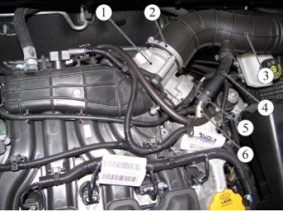
Figure 3-34 - Air cleaner with air supply pipe and intake pipe hose assembly: 1 - throttle pipe; 2 - intake pipe hose clamp; 3 - inlet pipe hose; 4 - upper crankcase ventilation hose; 5 - Upper crankcase ventilation hose clamp; 6 - crankcase ventilation pipe
Loosen the spring clamp 5, Figure 3-34, of the fastening and disconnect the upper hose 4 of the crankcase ventilation from the branch pipe 6 of the cylinder head cover (pliers).
Loosen clamp 2 and disconnect hose 3 of the intake pipe from throttle pipe 1 (phillips screwdriver).
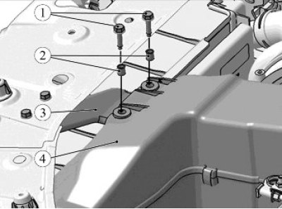
Figure 3-35 - Removing the intake resonator: 1 - bolt; 2 - spacer sleeve; 3 - resonator mounting bracket; 4 - intake resonator
Unscrew the two bolts 1, Figure 3-35, securing the intake resonator 4 to the bracket 3 (replacement head 10, ratchet).
Loosen the air filter mounting bolt and remove the air filter with the intake pipe hose and resonator assembly (replacement head 10, ratchet).
Unscrew nut 2, Figure 3-4, securing bracket 1 of the engine wiring harness to bracket 3 of the air filter and remove the wiring harness from the work area (replacement head 10, extension, ratchet).
Unscrew three nuts 1, Figure 3-5, and remove the air filter mounting bracket 2 (replacement head 10, extension, ratchet).
Disconnect the oxygen sensor wiring harness connector from the gearbox mounting bracket, remove the oxygen sensor wiring harness from the mounting bracket and remove the harness from the work area.
Remove the front wheels in accordance with the requirements of TI 3100.25100.20594.
Remove the engine mudguard, remove the front suspension subframe with the front suspension arms, anti-roll bar, steering rack and electric power steering pump as an assembly in accordance with the requirements of TI 3100.25100.20594.
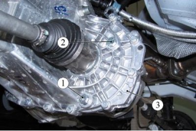
Figure 3-36 - Gearbox oil change hole plugs: 1 - oil drain plug; 2 - oil filler hole plug; 3 - gearbox
Unscrew plug 1, Figure 3-36, and drain the oil from the 3-speed gearbox (ring spanner 17, installation type 24164 brand "ALFA" (Italy) for collecting used oil).
Degrease the threads in the gearbox housing and on the plug, apply sealant to the threaded part of the plug (white spirit, consumption rate 2 g; sealant PS-1 according to the current "Codifier of main and auxiliary materials used in maintenance and repair of LADA vehicles" K 3100.25100.00018, consumption rate 1 g).
Screw plug 1 into the oil drain hole in the 3rd gearbox housing. Tightening torque of the plug 29.46 N·m (2.9...4.6 kgf·m) (replaceable head 17, ratchet, torque wrench).
Remove the clutch release mechanism actuator with the gearbox harness assembly in accordance with the requirements of Section 7 of this TI.
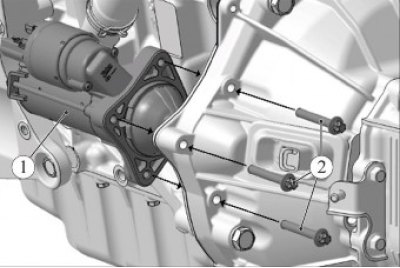
Figure 3-37 - Removing the starter: 1 - starter; 2 - mounting bolt
Unscrew the three bolts 2, Figure 3-37, that secure the starter and hang the starter 1 on the technological hook (technological hook, replaceable head Torx E1 0, extension, ratchet wrench).
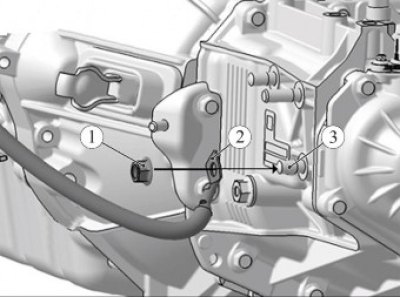
Figure 3-38 - Disconnecting the wiring harnesses from the gearbox: 1 - nut; 2 - "ground" wire terminal; 3 - pin for fixing the "mass" wire
Unscrew nut 1, Figure 3-38, securing terminal 2 of the ground wire to the gearbox and remove the ground wire from the work area (replacement head 17, ratchet).
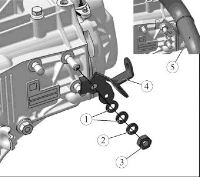
Figure 3-39 - Disconnecting the bracket securing the radiator outlet hose from the gearbox: 1 - flat washer; 2 - spring washer; 3 - nut; 4 - bracket; 5 - radiator outlet hose
Unscrew nut 3, Figure 3-39, securing the bracket, remove spring washer 2, two flat washers 1 and disconnect bracket 4 with hose 5 as an assembly from the gearbox (replacement head 17, extension, ratchet).
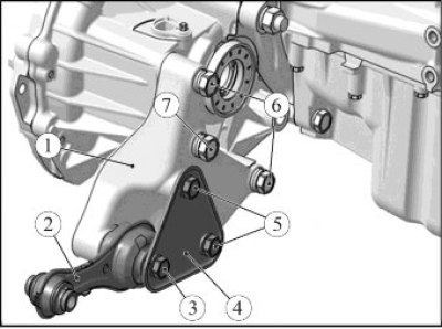
Figure 3-40 - Removing the rear engine mount bracket: 1 - rear suspension support bracket; 2 - rear suspension support rod; 3 - rod mounting bolt; 4 - amplifier; 5 - amplifier mounting bolt; 6 - bracket mounting bolt; 7 - bracket mounting bolt
Unscrew and remove two bolts 6, Figure 3-40, and bolt 7, remove flat and spring washers and remove bracket 1 of the rear engine mount support with rod 2 and reinforcement 4 as an assembly (replaceable head 18, ratchet).
Knock out and remove the inner joints of the front wheel drives from the differential axle gears and install transport plugs in their place (transport plugs - 2 pcs., mounting blade).
Install a crossbar on the engine compartment to support the engine, place a textile loop sling behind the engine tray, hook the crossbar hook onto the loops of the sling and support the engine (crossbar for hanging the engine, textile loop sling with a lifting capacity of 500 kg, sling length 2.0 meters).
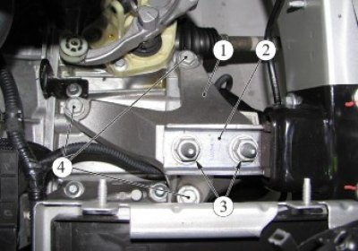
Figure 3-41 - Removing the left engine mount bracket: 1 - left engine mount bracket; 2 - left engine mount support; 3 - nuts for fastening the bracket to the support; 4 - bolts for fastening the left support to the gearbox
Unscrew the two nuts 3, Figure 3-41, securing bracket 1 to the left support 2 of the engine mount (replacement head 18, extension, ratchet).
Loosen and remove three bolts 4 securing bracket 1 of the left engine mount to the gearbox and remove the bracket (replacement head 16, extension, ratchet).
Lower the power unit on the engine support beam so that the rear cover of the gearbox drops slightly below the side member (engine support beam).
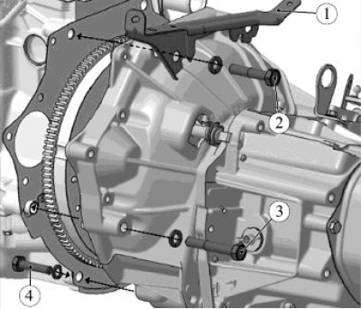
Figure 3-42 - Disconnecting the gearbox from the engine: 1 - wiring harness mounting bracket; 2 - upper bolt for fastening the gearbox to the engine; 3 - lower bolt for fastening the gearbox to the engine; 4 - bolt for fastening the gearbox to the engine crankcase
Unscrew and remove the two upper bolts 2, Figures 3-42, 3-43, together with the spring washers securing the gearbox to the engine and remove the bracket 1 together with the wiring harness from the work area (replaceable head 19, extension, ratchet wrench).
Bring the support part of the hydraulic transmission strut up to the stop against the gearbox (hydraulic transmission strut type SG-1 "GARO").
Loosen and remove two bolts 4, Figures 3-42, 3-43, together with spring washers securing the gearbox to the engine crankcase (replaceable head 17, ratchet wrench).
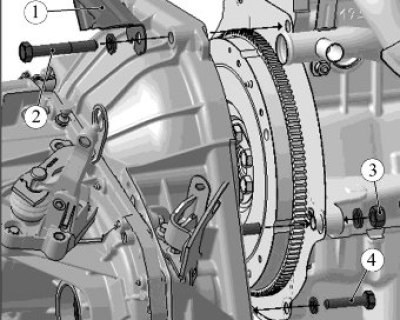
Figure 3-43 - Disconnecting the gearbox from the engine: 1 - wiring harness mounting bracket; 2 - upper bolt for fastening the gearbox to the engine; 3 - nut for fastening the gearbox to the engine; 4 - bolt for fastening the gearbox to the engine crankcase
Loosen and remove bolt 3, Figure 3-42, complete with spring washer and nut 3, Figure 3-43, with spring washer for fastening the gearbox to the engine (replaceable head 19, extension, ratchet wrench).
Remove the primary shaft of the gearbox from the splines of the driven clutch disc, lower the hydraulic strut with the gearbox down and remove it from under the vehicle (hydraulic transmission strut type SG-1 "GARO").
Caution: When performing the gearbox removal/installation operation, do not rest the input shaft on the clutch pressure spring petals to prevent damage to them.
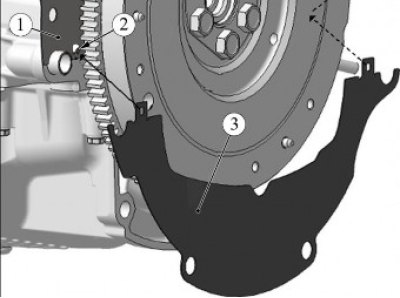
Figure 3-44 - Removing the lower clutch housing cover: 1 - upper clutch housing cover; 2 - hook; 3 - lower clutch housing cover
Remove cover 1 from hooks 2, Figure 3-32, cover 3 of the lower clutch housing.
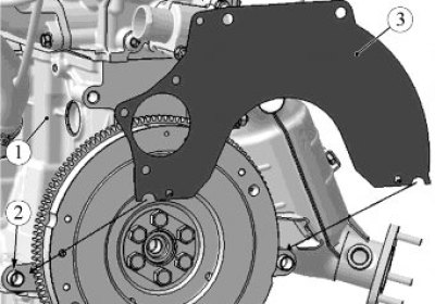
Figure 3-45 - Removing the upper clutch housing cover: 1 - engine; 2 - centering sleeve; 3 - upper clutch housing cover
Remove the upper clutch housing cover 3 from engine 1, Figure 3-33.
Install the gearbox on a workbench, remove the clutch release sleeve, remove the fork boot and the clutch release fork.
Installation
Check the condition of the front wheel drive seals and replace if necessary (flat head screwdriver, mandrel 67.7853-9562, hammer).
Apply to the contact surfaces of the clutch release fork (fork - clutch release sleeve, fork - fork ball joint) grease. Install the clutch release fork, fork boot and clutch release sleeve into the gearbox (Unioll-2M/1 grease according to the current "Codifier of main and auxiliary materials used in maintenance and repair of LADA vehicles" K 3100.25100.00018, consumption rate 4 g).
Install the upper clutch housing cover 3 on engine 1, Figure 3-45.
Install the lower clutch housing cover 3 on hooks 2, Figure 3-44.
Install the gearbox on the transmission stand and place it under the vehicle (hydraulic transmission stand type SG-1 "GARO").
Raise the support part of the transmission rack with the gearbox, insert the splined part of the primary shaft into the splines of the driven clutch disc and align the mounting holes on the gearbox and engine.
Screw in, without tightening, bolt 3, Figure 3-42, together with the spring washer and nut 3, Figure 3-43, with the spring washer for fastening the gearbox to the engine (replaceable head 19, extension, ratchet wrench).
Screw in, without tightening, two bolts 4, figures 3-42, 3-43, together with spring washers for fastening the gearbox to the engine crankcase (replaceable head 17, ratchet wrench).
Install bracket 1, figures 3-42, 3-43 for fastening the wiring harness and tighten the two bolts 2 for fastening the gearbox to the cylinder block with spring washers. Tightening torque of bolts 36...52 Nm (3.6...5.2 kgf·m) (replaceable head 19, ratchet, extension, torque wrench).
Finally tighten bolt 3, Figure 3-42, and nut 3, Figure 3-43, of the gearbox mounting stud to the cylinder block. Tightening torque of bolt and nut 36...52 Nm (3.6...5.2 kgf·m) (replaceable head 19, ratchet, extension, torque wrench).
Finally tighten the two bolts 4, Figures 3-42, 3-43, securing the gearbox to the engine crankcase. Tightening torque of bolts 36...52 Nm (3.6...5.2 kgf·m) (replaceable head 17, ratchet wrench, torque wrench).
Install bracket 1, Figure 3-41, of the left engine mount support onto the gearbox and tighten the three mounting bolts 4. Tightening torque of bolts 53...71 N·m (5.3...7.1 kgf·m) (replaceable head 16, ratchet and extension, torque wrench).
Attach the power unit to the left support 2 of the engine mount and tighten the two fastening nuts 3. Tightening torque of nuts 90...120 Nm (9.0...12.0 kgf·m) (replaceable head 18, ratchet and extension, torque wrench).
Remove the engine support beam from the vehicle.
Remove the old retaining rings from the inner drive joint ends of the wheel drives and install new rings in the groove centers. Reuse of retaining rings is not permitted.
Remove the transport plug from the gearbox differential. Insert the splined part of the inner joint of one of the drives into the axle shaft seal, turn the drive shaft and align the joint splines with the axle shaft gear recesses.
Press the drive into the axle shaft gear with a sharp movement of the rack with the steering knuckle.
Make sure that the drive is fixed in the axle shaft gear using your hands, applying a load to the inner joint towards the steering knuckle.
Perform installation operations for the other wheel drive.
Secure the oxygen sensor wiring harness connector to the gearbox mounting bracket and secure the oxygen sensor wiring harness to the mounting bracket.
Install bracket 4 with hose 5 assembled on the gearbox stud, install two flat washers 1, spring washer 3 and tighten fastening nut 3. Nut tightening torque 7...9 Nm (0.7...0.9 kgf·m) (replaceable head 17, extension, ratchet, torque wrench).
Install starter 1, Figure 3-37, and tighten the three mounting bolts 2. Tightening torque of bolts 22...28 Nm (2.2...2.8 kgf·m) (torx E10 socket, extension, ratchet, torque wrench).
Install the clutch release mechanism actuator and the gearbox wiring harness in accordance with the requirements of Section 7 of this TI.
Install the front suspension subframe with the front suspension arms, anti-roll bar, steering rack and electric power steering pump as an assembly in accordance with the requirements of TI 3100.25100.20594.
Install terminal 2 of the ground wire, Figure 3-38, on the gearbox stud and tighten the nut
1 fastener. Nut tightening torque 18...24 Nm (1.8...2.4 kgf·m) (replaceable head 17, ratchet, torque wrench).
Install bracket 1, Figure 3-40, the rear engine mount supports with rod 2 and amplifier 4 in assembly and tighten, without tightening, two mounting bolts 6 with flat and spring washers (replaceable head 18, ratchet).
Tighten bolt 7 with a flat and spring washer. Bolt tightening torque 53...71 Nm (5.3...7.1 kgf·m) (replaceable head 16, ratchet, torque wrench).
Finally tighten bolts 6 for mounting bracket 1. Tightening torque of bolts 90...120 N·m (9.0...12.0 kgf·m) (replaceable head 18, torque wrench).
Loosen bolt 3 of the rear suspension support rod 2 (replaceable head 18, ratchet).
Attach the rod 2 of the rear suspension support to the front suspension subframe, install the bolt and tighten the fastening nut. Bolt tightening torque 90...120 Nm (9.0...12.0 kgf·m) (replacement head 18, ring spanner 16, ratchet spanner, torque spanner).
Finally tighten bolt 3 securing rod 2 to bracket 1. Bolt tightening torque 90...120 N·m (9.0...12.0 kgf·m) (replaceable head 18, torque wrench).
Unscrew plug 2, Figure 3-36, to fill in oil (ring spanner 17, installation type 24164 brand "ALFA" (Italy) for collecting used oil).
Fill the gearbox with oil. The oil level should be at the lower edge of the filler hole (filling unit C-223-1 for transmission oils, transmission oil GL-4 according to API classification in accordance with the current "Codifier of main and auxiliary materials used in maintenance and repair of LADA vehicles" K 3100.25100.00018, consumption rate - 2.25 l).
Degrease the threads in the gearbox housing and on the plug, apply sealant to the threaded part of the plug (white spirit, consumption rate 2 g; sealant PS-1 according to the current "Codifier of main and auxiliary materials used in maintenance and repair of LADA vehicles" K 3100.25100.00018, consumption rate 1 g).
Screw plug 2, Figure 3-36, into the oil filler hole in the gearbox housing. Tightening torque of the plug 29...46 N·m (2.9...4.6 kgf·m) (replaceable head 17, ratchet, torque wrench).
Install the engine mudguard in accordance with the requirements of TI 3100.25100.20594.
Install the front wheels in accordance with the requirements of TI 3100.25100.20594.
Install the air filter with the intake pipe hose and resonator assembly on the vehicle.
Attach resonator 4, Figure 3-21, to the intake bracket 3, make sure that there are spacer bushings 2 and tighten the two mounting bolts. Tightening torque of bolts 7...9 Nm (0.7...0.9 kgf·m) (replaceable head 10, ratchet, torque wrench).
Connect hose 3, Figure 3-20, of the intake pipe to the throttle pipe 1, install and tighten clamp 2 of the fastening (phillips screwdriver).
Connect the upper hose 4 of the crankcase ventilation to the branch pipe of the cylinder head cover and secure it with the spring clamp 5 of the fastening (pliers).
Tighten the air filter mounting bolt. Bolt tightening torque 7...9 Nm (0.7...0.9 kgf·m) (replaceable head 10, ratchet, torque wrench).
Install battery 1 on the vehicle, Figure 3-1, install clamping bar 7 and tighten mounting bolt 6. Bolt tightening torque 11...13 Nm (1.1...1.3 kgf·m) (replaceable head 13, extension, ratchet, torque wrench).
Connect terminal 3 of the ground wire and terminal 4 of the positive wire to the battery and tighten nuts 2 and 5. Tightening torque of nuts 4...6 Nm (0.4...0.6 kgf·m) (replaceable head 10, torque wrench).
Check and, if necessary, adjust the front wheel alignment angles in accordance with the requirements of TI 3100.25100.13070.
Present the vehicle to the Quality Control Department. The Quality Control Department will check the vehicle for compliance with the requirements of TU 017200-254-00232934, paragraphs 1.19.8, 1.19.15, 1.19.16, 1.19.17, 1.19.21.3.