



Attention: When performing operations of removing/installing the gearshift actuator, it is not allowed:
- disassembly of the actuator, except in cases where it is impossible to remove the actuator from the gearbox without disassembly;
- actuator fall, in case of fall replace the actuator with a new one;
- connect the actuator to the power supply and operate it outside the gearbox;
- rotate the actuator manually by shaft 2, figure 6-1, or gear shift lever 4;
- hold the actuator by the 2 gearshift shaft end or the locking plate 3;
- touching the actuator connector contacts with ungrounded objects or hands (sensors may be damaged due to electrostatic discharge).
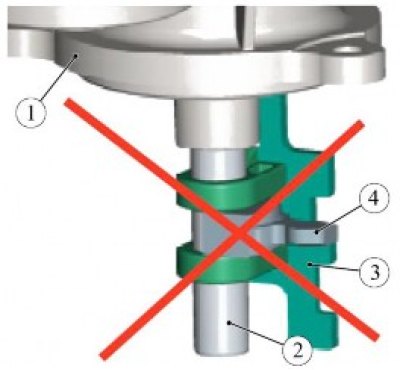
Figure 6-1 - Removing the gearshift actuator: 1 - gear shift actuator; 2 - gear shift lever shaft; 3 - locking plate; 4 - gear shift lever
Attention: The actuator is not repairable. If any defect is detected, the actuator is checked, repaired or replaced by ZF.
Caution: Position of the actuator gearshift lever when installed on the gearbox (in delivery condition) selection - 3/4 gear line, switching - neutral.
Removal
Place the vehicle on a two-post lift and apply the parking brake (two-post lift type P3.2G with a lifting capacity of 3.2 t).
Remove the air filter with the intake pipe hose and the air supply pipe assembly in accordance with the requirements of Section 3 of this TI.
Set the gearshift actuator to neutral in one of the following ways:
- 1 - using a diagnostic tool;
- 2 - turn on the ignition, press the brake pedal and move the gearshift control lever to the neutral position, turn off the ignition and wait for the control controller to turn off - 1 min.
If the actuator cannot be set to the neutral position, it is necessary to check the reliability of the connection of the wiring harness connectors to the connectors on the actuator, on the control controller and on the control drive. Check the reliability of the connection of the wiring harness connector to the brake light switch. Check the wire harnesses for breaks, damaged insulation and short circuits. Conduct diagnostics of the robotic gearbox in accordance with the requirements of TI 3100.25100.12055.
Disconnect the ground wire terminal from the battery (spanner 10).
Disconnect the transmission wiring harness connectors from the gearshift actuator connectors.
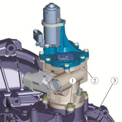
Figure 6-2 - Removing the gear shift actuator: 1 - actuator mounting bolts; 2 - gear shift actuator; 3 - gearbox
If the gearshift actuator is set to neutral, unscrew the three bolts 1, Figure 6-2, and remove the actuator 2 from the gearbox 3 (ring spanner 13).
Inspect the working parts of the actuator (shaft and gear shift lever, locking plate) and make sure there is no damage.
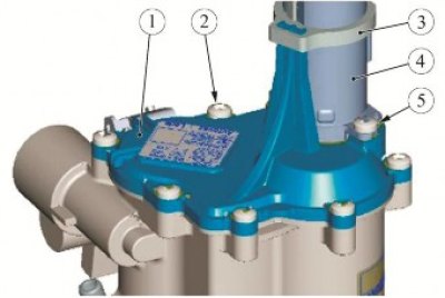
Figure 6-3 - Removing a faulty shift actuator: 1 - actuator cover; 2 - actuator mounting screw; 3 - Electric motor mounting clamp; 4 - upper actuator electric motor; 5 - electric motor mounting screw
If diagnostics reveal a faulty actuator and the actuator shift lever is in a position other than the "neutral" position, remove the actuator in the following sequence:
- unscrew the two screws 5, Figure 6-3, securing the upper electric motor to the actuator cover and remove the electric motor 4 assembled with the clamp 3 securing it (torx T30 replaceable bit, ratchet);
- unscrew the seven screws 2 securing the top cover of the actuator and remove the cover 1 (torx T30 replaceable bit, ratchet);
- try to manually move the toothed sector 1, Figure 6-4, to the neutral position (for example, in the case where there is a failure of the upper electric motor);
- unscrew the three mounting bolts and try to remove the actuator from the gearbox (ring spanner 13).
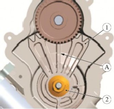
Figure 6-4 - Removing a faulty shift actuator: 1 - toothed sector of the gear shift lever shaft; 2 - toothed sector fastening nut; A - the orientation of the toothed sector corresponds to the "neutral" position
If the actuator cannot be removed from the gearbox, the following additional operations must be performed:
- unscrew nut 2 of the toothed sector fastening (replaceable head 13, ratchet);
- remove actuator from gearbox (the gear shift shaft remains in the gearbox, so significant force must be applied to remove the actuator);
- remove the gear shift shaft from the box.
Remove the breather cap from the actuator.
Clean the mating surfaces on the gearbox and actuator from old sealant (plastic scraper, brush, white spirit).
Clean the threaded part of the two M8x25 actuator mounting bolts and the corresponding holes in the gearbox housing and degrease (brush, white spirit, consumption rate 5 g).
Installation
Before installing the gearshift actuator, perform the following operations:
- in the gearbox, check the position of the gear shift fork rods and, if necessary, set the rods to the "neutral" position;
- apply liquid gasket PS-1 to the mating surface of the gearbox under the actuator with a continuous roller with a diameter of 2 mm in accordance with the current "Codifier of the main and auxiliary materials used in the maintenance and repair of LADA vehicles" K 3100.25100.00018, consumption rate 5 g;
- apply sealant to the two M8x25 actuator mounting bolts in a 3 mm wide band in accordance with the diagram shown in Figure 6-5 (Loctite 5061 sealant in accordance with the current "Codifier of main and auxiliary materials used in maintenance and repair of LADA vehicles" K 3100.25100.00018, consumption rate 2 g).
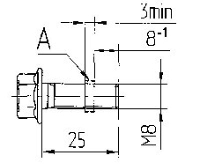
Figure 6-5 - Scheme for applying sealant to actuator mounting bolts: A - sealant application area
Install the gearshift actuator into place and secure it with three bolts. Tightening torque of bolts 16...25 Nm (1.6...2.5 kgf·m) (ring spanner 13, replaceable nozzle 13, torque wrench).
Replace the breather cap.
Connect the transmission wiring harness connectors to the gearshift actuator connectors.
Install the air filter with the intake pipe hose and the air supply pipe assembly in accordance with the requirements of Section 3 of this TI.
Connect the ground wire terminal to the battery and tighten the mounting nut. Tightening torque of the nut 4...6 Nm (0.4...0.6 kgf·m) (replaceable head 10, torque wrench).
Perform the AMT training procedure in accordance with the requirements of TI 3100.25100.12055.
Present the vehicle to the Quality Control Department. The Quality Control Department will check the vehicle for compliance with the requirements of TU 017200-254-00232934, paragraphs 1.19.8, 1.19.15, 1.19.16, 1.19.17, 1.19.21.3.