



Attention: When performing operations of removing/installing the clutch release mechanism actuator, it is not allowed:
- disassembling the actuator and removing the rubber seal of the rod;
- actuator fall, in case of fall replace the actuator with a new one;
- connect the actuator to the power supply and operate it without load;
- hold the actuator by the rod or rubber cuff;
- manually push the rod into the actuator body if the rod is extended;
- touch the actuator connector contacts with ungrounded objects or hands (sensors may be damaged due to electrostatic discharge).
Attention: The actuator is not repairable. If any defect is detected, the actuator is checked, repaired or replaced by ZF.
Removal
Place the vehicle on a two-post lift and apply the parking brake (two-post lift type P3.2G with a lifting capacity of 3.2 t).
[Material was taken from the website: www.LadaMan.ru]
Ensure that the actuator is in the "clutch engaged" position by performing the following procedures:
- turn off the ignition and wait for the robotic gearbox controller to turn off - 1 min.;
- make sure the clutch is fully engaged (the actuator pusher is pressed against the clutch fork with a small load, approximately 25.50 N);
- if the actuator does not return to the "clutch engaged" position, press the brake pedal, turn on the ignition, wait at least 10 seconds, turn off the ignition again and wait for the control controller to turn off;
- if the actuator cannot be set to the "clutch engaged" position, it is necessary to check the reliability of the connection of the wiring harness pads to the connectors on the actuator and on the control controller. Check the reliability of the connection of the wiring harness connector to the brake light switch. Check the wire harnesses for breaks, damaged insulation and short circuits. Conduct diagnostics of the robotic gearbox in accordance with the requirements of TI 3100.25100.12055.
Disconnect the ground wire terminal from the battery (spanner 10).
Remove the air filter with the intake pipe hose and the air supply pipe assembly in accordance with the requirements of Section 3 of this TI.
Remove the engine mudguard in accordance with the requirements of TI 3100.25100.20594.
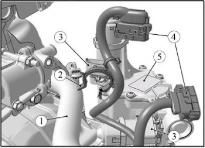
Figure 7-1 - Disconnecting the transmission wiring harness: 1 - radiator outlet hose; 2 - bracket for fastening the gearbox wiring harness to the radiator outlet hose; 3 - actuator connectors; 4 - pads of the gearbox wiring harness to the gearshift actuator; 5 - gear shift actuator
Disconnect pads 4, Figure 7-1, of the gearbox wiring harness from connectors 3 of actuator 5 of the gear shift mechanism.
Remove the bracket 2 securing the gearbox wiring harness from the hose 1 of the radiator outlet.
Disconnect the transmission wiring harness connector from the engine wiring harness connector.
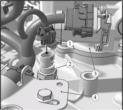
Figure 7-2 - Disconnecting the transmission wiring harness: 1 - gearbox wiring harness connector; 2 - Reverse light switch; 3 - gear shift actuator; 4 - Clutch release mechanism actuator
Disconnect connector 1, Figure 7-2, of the gearbox wiring harness from switch 2 of the reverse light.
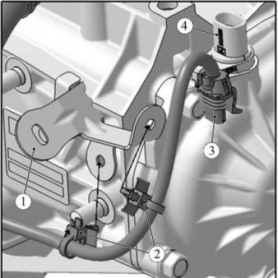
Figure 7-3 - Disconnecting the transmission wiring harness: 1 - bracket; 2 - mounting clamp; 3 - gearbox wiring harness connector; 4 - primary shaft speed sensor
Disconnect block 3, Figure 7-3, of the gearbox wiring harness from sensor 4 of the primary shaft speed and disconnect or cut off clamps 2 securing the harness to bracket 1.
Caution: When removing the clutch release actuator, be careful; when unscrewing the mounting bolts, the actuator may move spontaneously.
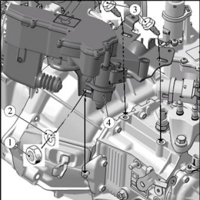
Figure 7-4 - Removing the clutch release actuator: 1 - nut; 2 - spring washer; 3 - bolt; 4 - clutch release mechanism actuator with mounting bracket assembly
Loosen nut 1, Figure 7-4, and two bolts 3 securing the actuator bracket to relieve the load from the actuator rod. Finally, unscrew the nut and mounting bolts and remove the clutch release actuator 4 with the bracket and the gearbox wiring harness as an assembly (replaceable head 13, extension, ratchet wrench).
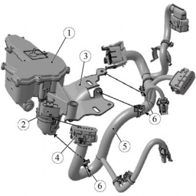
Figure 7-5 - Disconnecting the transmission wiring harness: 1 - Clutch release mechanism actuator; 2 - connector; 3 - actuator mounting bracket; 4 - block of the wiring harness of the gearbox to the clutch actuator; 5 - additional wiring harness; 6 - clamp for fastening the gearbox wiring harness to the actuator mounting bracket
Disconnect block 4, Figure 7-5, from connector 2 of actuator 1 of the clutch release mechanism, disconnect from bracket 3 or cut off clamps 6 securing harness 5 of additional wires and remove the harness.
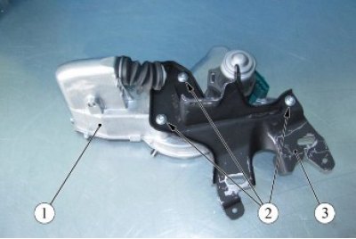
Figure 7-6 - Removing the actuator bracket: 1 - Clutch release mechanism actuator; 2 - screws for fastening the actuator to the bracket; 3 - actuator mounting bracket
Unscrew the three self-tapping screws 2, Figure 7-6, securing the actuator to the bracket and remove the bracket 3 from the actuator 1 (torx T30 replaceable bit, ratchet).
Installation
Install the actuator 1, Fig. 7-6, for disengaging the clutch on the bracket 3 and tighten the three self-tapping screws 2. The tightening torque of the screws is 7...12 N·m (0.7...1.2 kgf·m) (torx T30 replacement bit, ratchet, torque wrench).
Connect block 4, figure 7-5, of the gearbox wiring harness to connector 2 of actuator 1 of the clutch release mechanism and secure harness 5 to bracket 3 with clamps 6 (if the clamps built into the wiring harness have been cut, then use clamp 21230-3724308-00 to install the wiring harness).
Install the actuator 4, Figure 7-4, clutch release assembly with the bracket and wiring harness on the gearbox and tighten, without tightening, two bolts 3 and nut 1 of the fastening (replaceable head 13, ratchet).

Figure 7-7 - Installing the clutch release actuator: 1, 2 - actuator mounting bolts to the gearbox; 3 - actuator mounting nut to gearbox; 4 - actuator mounting bracket; 5 - Clutch release mechanism actuator; 6 - actuator rod; 7 - clutch release fork
Adjust the extension of rod 6, Figure 7-7, of the actuator, for which it is necessary:
- move actuator 5 in the direction of the arrow until rod 6 touches clutch release fork 7 and mark the position of bracket 4 relative to the gearbox without impact;
- using the mark, additionally move the actuator in the direction of the arrow by 6±2 mm and finally tighten the two bolts 1 and 2 and the fastening nut 3. Tightening torque of bolts and nuts 16...25 Nm (1.6...2.5 kgf·m) (replaceable head 13, ratchet, torque wrench, ruler or caliper).
Connect the transmission wiring harness connectors to the gearshift actuator connectors, to the reverse light switch, to the input shaft speed sensor and to the engine wiring harness connector.
Secure the gearbox wiring harness with clamps built into the harness on bracket 1, Figure 7-3, and with clamp 2, Figure 7-1, on the radiator outlet hose (if the clamps built into the wiring harness have been cut, then use clamp 21230-3724308-00 to install the wiring harness).
Install the air filter with the intake pipe hose and the air supply pipe assembly in accordance with the requirements of Section 3 of this TI.
Install the engine mudguard in accordance with the requirements of TI 3100.25100.20594.
Connect the ground wire terminal to the battery and tighten the mounting nut. Tightening torque of the nut 4...6 Nm (0.4...0.6 kgf·m) (replaceable head 10, torque wrench).
Perform the AMT training procedure in accordance with the requirements of TI 3100.25100.12055.
Present the vehicle to the Quality Control Department. The Quality Control Department will check the vehicle for compliance with the requirements of TU 017200-254-00232934, paragraphs 1.19.15, 1.19.16, 1.19.21.3.