
Removing
Put the car on a two post lift (electrohydraulic hoist type P-3.2 G with a lifting capacity of 3.2 tons).
Apply the parking brake, turn off the ignition, raise the hood.
Remove battery.
Remove air filter.
Remove the front bumper.
Disconnect the instrument panel harness connectors from the right and left headlights.
Disconnect all connectors of the instrument panel wiring harness from the electrical consumers in the engine compartment.
Loosen nuts and remove terminals 1, figures 19-1 and 19-6, wires "masses" instrument panel wiring harness from the car body next to the right and left headlights (wrench "on 10").
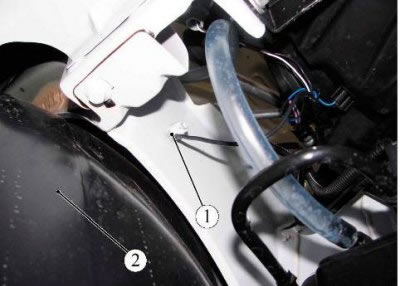
Figure 19-1 - Disconnecting the wire "masses" instrument panel wiring harness from the right front wheel arch: 1 - wire terminal "masses" instrument panel wiring harness; 2 - protective casing of the wheel arch, right
Disconnect connector 2, Figure 9-1, instrument panel wiring harness from horn 3.
Remove trim 1, Figure 19-2, right and left windscreen frames 1, Figure 19-3.
Disconnect connector 1, Figure 19-4, instrument panel wiring harness from windshield washer motor 2.
Disconnect connector 1, Figure 19-5, of the wiring harness from the brake fluid level sensor.
Disconnect the wiring harness terminal 2 from the wiper motor.
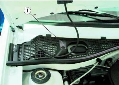
Figure 19-2 - Right windshield frame trim: 1 - facing of a frame of a wind window right
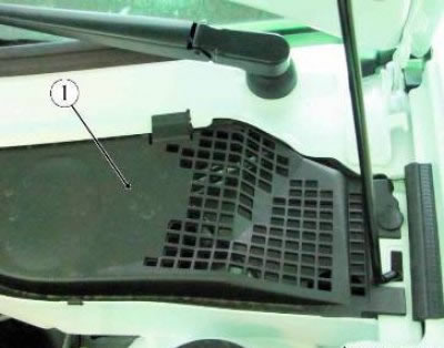
Figure 19-3 - Left windshield frame trim: 1 - facing of a frame of a wind window left
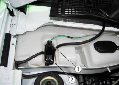
Figure 19-4 - Windshield washer reservoir: 1 - block of the wiring harness to the windshield washer motor; 2 - windshield washer motor
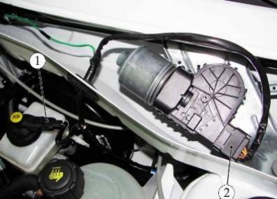
Figure 19-5 - Disconnecting the instrument panel harness connectors from the wiper motor and brake fluid level sensor: 1 - block of the wiring harness to the brake fluid level sensor; 2 - block of the wiring harness to the wiper motor
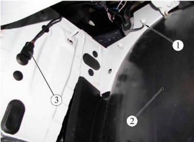
Figure 19-6 - Disconnecting the wire "masses" instrument panel wiring harness from the left front wheel arch: 1 - wire terminal "masses" instrument panel wiring harness; 2 - protective casing of the wheel arch, left; 3 - block of the wiring harness of the instrument panel to the block of the wiring harness of the front bumper
Disconnect the instrument panel wiring harness connector 3 from the front bumper wiring harness connector.
Disconnect in the mounting block 1, Figure 19-7, fuse blocks 4, 5, 7 and relays 3, 6 from the body of the mounting block.
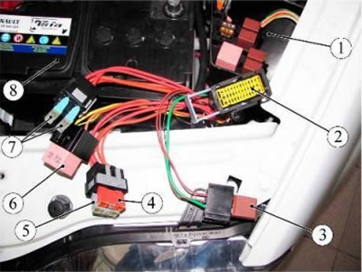
Figure 19-7 - Mounting block in the engine compartment: 1 - mounting block; 2 - block of the wiring harness of the instrument panel to the block of the wiring harness of the ignition system; 3 - relay; 4 - fuse 50 A; 5 - fuse 25 A; 6 - relay; 7 - fuses 60 A; 8 - battery
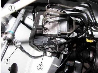
Figure 19-8 - ABS computer (anti-lock braking system electronic control unit): 1 - ABS computer; 2 - block of the instrument panel wiring harness to the ABS computer; 3 - wire terminal nut "masses" instrument panel wiring harness
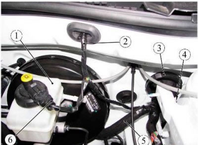
Figure 19-9 - Instrument panel wiring harness: 1 - a reservoir of a hydraulic drive of brakes; 2 - instrument panel wiring harness to the wiper motor; 3 - sealing ring; 4 - a branch of the instrument panel wiring harness to the left front speed sensor; 5 - a branch of the instrument panel wiring harness to the ABS computer and the right front speed sensor; 6 - block of the instrument panel wiring harness to the brake fluid level sensor
Disconnect the harness block connector from the body of the mounting block and the instrument panel wiring harness block 2 from the ignition system wiring harness block.
Remove expansion tank 2, Figure 3-1.
Disconnect connector 2, Figure 19-8, instrument panel harness from ABS computer 1.
Unlock and unscrew the nut 3 wire terminals "masses" instrument panel wiring harness.
Remove the protective cover of the right wheel arch.
Disconnect connector 1, Figure 19-10, instrument panel wiring harness from right front speed sensor.
Disconnect pointer 1, Figure 19-11, turning the side right from block 2 of the instrument panel wiring harness.
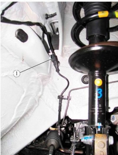
Figure 19-10 - Instrument panel wiring harness block: 1 - block of the instrument panel wiring harness to the right front speed sensor
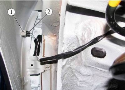
Figure 19-11 - Instrument panel wiring harness block: 1 - direction indicator side right; 2 - block wiring harness of the instrument panel
Disconnect all instrument panel connectors from the instrument panel harness connectors and remove the instrument panel.
Press the plastic retainer and remove the sealing ring 3, Figure 19-9.
Remove the front door trim.
Disconnect the connectors 2, Figure 19-12, of the instrument panel wiring harness from the front right and left front door loudspeakers.
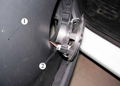
Figure 19-12 - Disconnecting the instrument panel wiring harness from the front speaker: 1 - front door; 2 - block of the wiring harness of the instrument panel to the front loudspeaker
Disconnect the pads 1, Figure 19-13, of the instrument panel wiring harness from the locks of the right and left front doors.
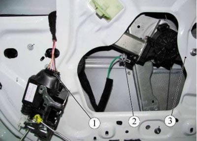
Figure 19-13 - Disconnecting the instrument panel harness from the front door lock and power window motor: 1 - block of the instrument panel wiring harness to the front door lock; 2 - block of the instrument panel wiring harness to the power window motor; 3 - front door
Disconnect the instrument panel harness connector 2 from the right and left front door power window motors.
Loosen the nut and remove terminal 1, figure 19-14, wires "masses" instrument panel wiring harness (wrench "on 10").
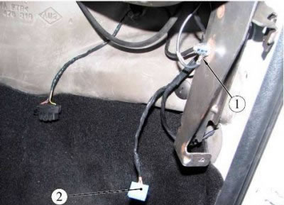
Figure 19-14 - Fastening the wire terminal "masses" instrument panel wiring harness: 1 - wire terminal "masses" instrument panel wiring harness; 2 - block of the wiring harness of the instrument panel to the block of the wiring harness of the glove box
Disconnect connector 5, Figure 19-15, of glove box harness from instrument panel harness connector.
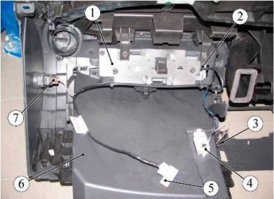
Figure 19-15 - Glove box wiring harness: 1 - passenger airbag; 2 - a block of a plait of wires of a ware box to an airbag of the passenger; 3 - sensor for turning on the light in the glove box; 4 - cover for lighting the glove box; 5 - block of the wiring harness of the glove box to the block of the wiring harness of the instrument panel; 6 - glove box; 7 - passenger airbag lock switch
Disconnect connector 1, Figure 19-16, of the heater motor harness from connector 2 of the instrument panel wiring harness.
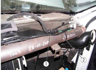
Figure 19-16 - Instrument panel wiring harness: 1 - block of the heater electric motor harness to the block of the instrument panel wiring harness; 2 - block of the wiring harness of the instrument panel to the block of the wiring harness of the heater electric motor
Unscrew the two nuts, and remove the two terminals 1 and 2, Figure 19-17, wires "masses" instrument panel wiring harness (wrench "on 10").
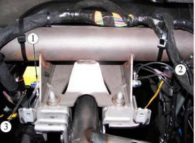
Figure 19-17 - Instrument panel wiring harness: 1, 2 - wire terminal "masses" instrument panel wiring harness; 3 - block of the instrument panel wiring harness to the rear window heating relay
Disconnect the instrument panel harness connector 3 from the heated rear window relay.
Disconnect connector 1, Figure 19-18, instrument panel harness from the brake light switch.
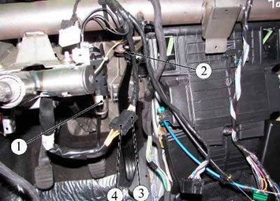
Figure 19-18 - Instrument panel wiring harness: 1 - block of the instrument panel wiring harness to the brake light switch; 2 - block of the wiring harness of the instrument panel to the additional resistor of the heater fan; 3 - block wiring harness of the instrument panel; 4 - block of the ignition switch to the block of the wiring harness of the instrument panel
Disconnect the instrument panel wiring harness connector 2 from the heater fan auxiliary resistor.
Disconnect the ignition switch connector 4 from the instrument panel wiring harness connector 3.
Remove the left sun visor, detach the front part of the roof lining and move it to the side.
Disconnect connector 1, Figure 12-3, of the instrument panel wiring harness from the dome light.
Remove the branch of the instrument panel wiring harness from the dome light.
Remove floor tunnel lining.
Disconnect the connector 1, Figure 19-19, instrument panel wiring harness from the cigarette lighter.
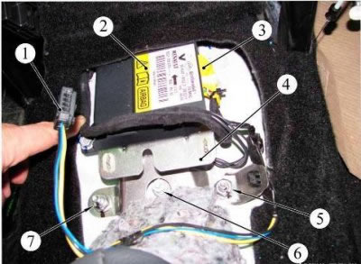
Figure 19-19 - Airbag computer: 1 - block of the instrument panel wiring harness to the cigarette lighter; 2 - airbag computer; 3 - block of the instrument panel wiring harness to the airbag computer; 4 - bracket for fastening the lining of the floor tunnel; 5 - bracket fastening nut; 6 - nut for fastening the wire terminal "masses" instrument panel wiring harness; 7 - bracket fastening nut
Disconnect the instrument panel harness connector 3 from the airbag computer 2.
Unscrew two nuts 5, 7 fastening the bracket 4 of the floor tunnel lining (interchangeable head 13, knob).
Remove the bracket for the floor tunnel lining.
Unscrew the nut 6 fastening the wire terminal "masses" instrument panel wiring harness (interchangeable head 10, knob).
Remove wire clamp "masses" instrument panel wiring harness.
Disconnect connector 1, Figure 19-20, instrument panel harness from handbrake switch.
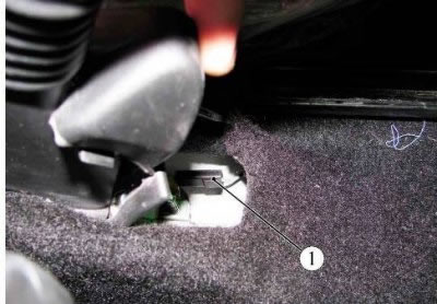
Figure 19-20 - Handbrake warning switch: 1 - block wiring harness of the instrument panel
Disconnect connector 1, Figure 19-21, seat heating harness connector from instrument panel harness connector.
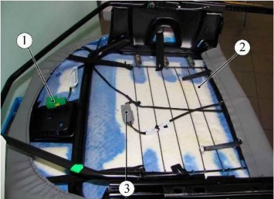
Figure 19-21 - Seat heating harness: 1 - block of the wiring harness for seat heating to the block of the wiring harness of the instrument panel; 2 - front seat; 3 - block of the seat heating wire harness to the block of the seatback
Remove front seat 2.
Disconnect connector 4, Figure 19-22, instrument panel harness from connector 3 of the seat heating switch.
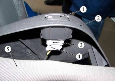
Figure 19-22 - Disconnecting the Instrument Panel Harness from the Heated Seat Switch: 1 - seat heating switch; 2 - front seat lining; 3 - seat heating switch connector; 4 - block wiring harness of the instrument panel; 5 - front seat
Remove the left and right B-pillar upholstery.
Unscrew two screws 2, Figure 14-2, fastening the mounting block 1 in the car to the bracket (interchangeable head Torx Т20, knob).
Remove mounting block.
Disconnect the two terminals 2 and 3, Figure 19-23, of the instrument panel wiring harness from the UCH 1.
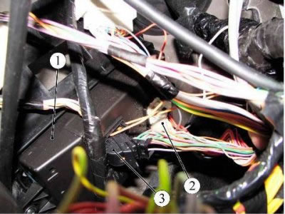
Figure 19-23 - UCH (central electronic switching unit in saloon): 1 - UCH; 2, 3 - pads of the wiring harness of the instrument panel to the pads of the UCH
Disconnect connector 2, Figure 19-24, instrument panel harness from HVAC control unit 1.
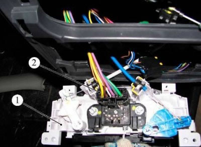
Figure 19-24 - Heating, air conditioning and ventilation control unit: 1 - control unit for heating, air conditioning and ventilation; 2 - block wiring harness of the instrument panel
Disconnect connector 1, Figure 19-25, instrument panel wiring harness from heater fan 2.
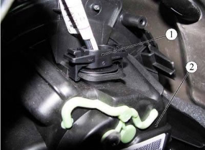
Figure 19-25 - Heater fan: 1 - block of the instrument panel wiring harness to the heater fan; 2 - heater fan
Disconnect the two terminals 1 and 2, Figure 20-1, of the rear wiring harness from the instrument panel wiring harness terminals.
Remove the instrument panel wiring harness.
Installation
Install the instrument panel wiring harness in the reverse order of removal.
At the same time, the tightening torque of the nuts for fastening the wire terminals "masses" instrument panel wiring harness 8 Nm (0.8 kgf·m) (interchangeable head 10, knob, torque wrench).