
Removing
Place the vehicle on a two-post lift, apply the parking brake and turn off the ignition, (electrohydraulic hoist type P-3.2 G with a lifting capacity of 3.2 tons).
Remove battery 1, Figure 21-1.
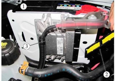
Figure 21-1 - Electronic control unit (ECM): 1 - battery; 2 - block of the wiring harness of the ignition system to the ECM; 3 - electronic control unit (ECU)
Remove air filter.
Disconnect three fuse blocks 6, 7 and 8 in the mounting block of the engine compartment, Figure 21-2, five relay blocks 4 and 5. Disconnect the latch 2.
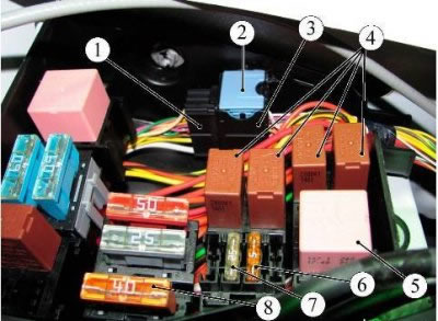
Figure 21-2 - Mounting block in the engine compartment: 1 - block of the wiring harness of the ignition system; 2 - latch; 3 - front wiring harness block; 4 - relay; 5 - relay; 6 - fuse 5 A; 7 - fuse 25 A; 8 - fuse 40 A
Disconnect block 1 of the ignition system wiring harness and block 3 of the instrument panel wiring harness from the body of the mounting block, disconnect the blocks.
Disconnect the latch on the mounting block box.
Disconnect connector 2, Figure 21-1, ignition harness from ECU 3.
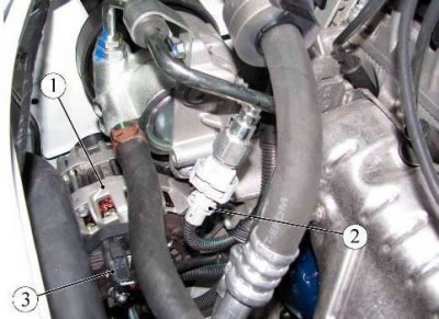
Figure 21-3 - Ignition wiring harness: 1 - generator; 2 - block of the wiring harness of the ignition system to the pressure sensor in the power steering system; 3 - block of the wiring harness of the ignition system to the generator
Unscrew the nut 1, Figure 4-1, fastening the wire to the B+ terminal of the generator and disconnect the block 3, Figure 21-3, of the ignition wiring harness from the generator 1.
Disconnect the ignition harness connector 2 from the power steering pressure sensor.
Disconnect the ignition harness connector from idle speed control 2, Figure 21-4.
Disconnect the ignition harness connectors from the injectors 3.
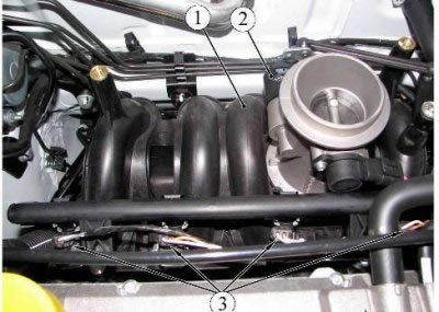
Figure 21-4 - Intake manifold: 1 - intake manifold; 2 - idle speed regulator; 3 - nozzles
Disconnect connector 1, Figure 21-5, of the ignition harness from the throttle position sensor.
Disconnect the ignition harness connector 2 from the intake air temperature sensor.
Disconnect the ignition harness connector 3 from the intake manifold air pressure sensor.
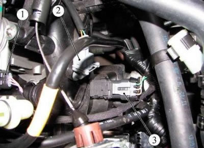
Figure 21-5 - Throttle position sensor: 1 - block of the wiring harness of the ignition system to the block of the throttle position sensor; 2 - block of the wiring harness of the ignition system to the intake air temperature sensor; 3 - block of the wiring harness of the ignition system to the air pressure sensor in the intake manifold
Disconnect connector 1, Figure 21-6, ignition harness from ignition coil 3.
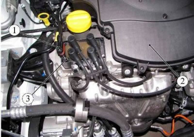
Figure 21-6 - Ignition coil: 1 - block of the wiring harness of the ignition system to the ignition coil; 2 - air filter; 3 - ignition coil
Disconnect the sensor block 1, Figure 21-7, oxygen control, standing on the exhaust manifold, from the ignition harness.
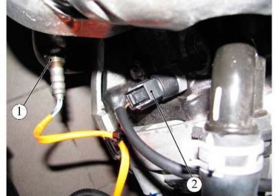
Figure 21-7 - Oil pressure sensor: 1 - control oxygen sensor; 2 - block of the wiring harness of the ignition system to the oil pressure sensor
Disconnect the ignition harness connector 2 from the oil pressure sensor.
Disconnect connector 1, Figure 21-8, of the ignition harness from the booster resistor.
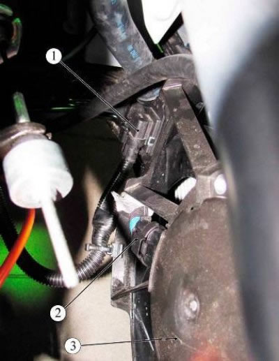
Figure 21-8 - Electric fan of the engine cooling system: 1 - block of the wiring harness of the ignition system to the additional resistor; 2 - block of the wiring harness of the ignition system to the electric fan; 3 - electric fan
Disconnect the ignition harness connector 2 from the engine cooling fan.
Remove the front bumper.
Raise the vehicle to a comfortable working height.
Remove the engine crankcase protection.
Disconnect connector 1, Figure 21-9, of the ignition harness from the diagnostic oxygen sensor.
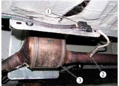
Figure 21-9 - Diagnostic oxygen sensor: 1 - block of the wiring harness of the ignition system to the diagnostic oxygen sensor; 2 - diagnostic oxygen sensor; 3 - catalytic converter
Disconnect connector 2, Figure 21-10, ignition harness from refrigerant pressure sensor 3.
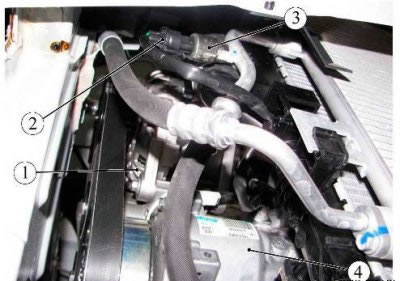
Figure 21-10 - Refrigerant pressure sensor: 1 - generator; 2 - block of the wiring harness of the ignition system; 3 - refrigerant pressure sensor; 4 - compressor
Disconnect connector 2, Figure 21-11, ignition harness from connector 1 of compressor clutch 3.
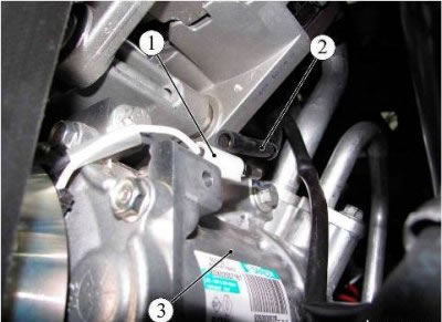
Figure 21-11 - Air conditioner compressor: 1 - compressor clutch block; 2 - block of the wiring harness of the ignition system; 3 - compressor
Loosen bolt 2, Figure 21-12, securing terminal 3 of the wire "masses" wiring harness of the ignition system and disconnect the terminal (wrench "at 13").
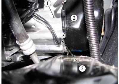
Figure 21-12 - Wire "masses" ignition wiring harness: 1 - gearbox; 2 - fastening bolt; 3 - wire terminal "masses" ignition wiring harness
Disconnect connector 1, Figure 21-13, of the ignition harness from the vehicle speed sensor.
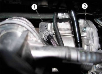
Figure 21-13 - Vehicle speed sensor: 1 - block of the wiring harness of the ignition system to the vehicle speed sensor; 2 - gearbox
Disconnect connector 2, Figure 21-14, of the ignition harness from the knock sensor.
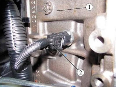
Figure 21-14 - Knock sensor: 1 - cylinder block; 2 - block of the wiring harness of the ignition system to the knock sensor
Disconnect the ignition harness connector from sensor 1, Figure 21-15, Reverse Engagement.
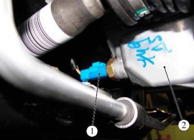
Figure 21-15 - Reverse speed switch: 1 - rear speed enable sensor; 2 - gearbox
Disconnect connector 2, Figure 21-16, of the ignition harness from the coolant temperature sensor.
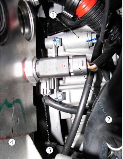
Figure 21-16 - Engine crankshaft position and speed sensor: 1 - gearbox; 2 - block of the wiring harness of the ignition system to the coolant temperature sensor; 3 - block of the wiring harness of the ignition system to the position and speed sensor of the engine crankshaft; 4 - engine
Disconnect the ignition harness connector 3 from the engine speed and position sensor.
Disconnect the ignition harness from the starter.
Lower the car.
Remove the ignition wiring harness.
Installation
Install the ignition harness in the reverse order of removal.
At the same time, the tightening torque of the wire terminal bolt "masses" on gearbox 21 Nm (2.1 kgf·m) (interchangeable head 13, knob, torque wrench).