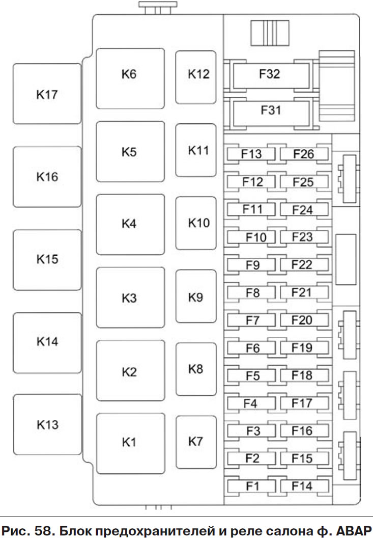
Table 4. Electrical circuits protected by fuses located in the fuse box and vehicle interior relay versions «norm/lux» *
| fuse no | Denomination | Protected circuits |
| F1 | 15A | Ignition coils |
| nozzles | ||
| Engine management system controller | ||
| F2 | 25A | Central body electronics |
| Driver door module | ||
| F3 | 15A | Automatic transmission control controller |
| Automatic transmission control drive | ||
| F4 | 15A | Controller of the inflatable airbag system |
| F5 | 7.5A | Terminal 15 devices |
| F6 | 7.5A | reversing light |
| Automatic transmission control controller | ||
| Safe Parking Control Unit | ||
| F7 | 7.5A | Canister purge valve |
| Mass Air Flow Sensor / Pressure Sensor | ||
| Phase sensor | ||
| Oxygen concentration sensors | ||
| F8 | 25A | Rear window heater |
| Exterior mirror heaters | ||
| F9 | 5A | Marker lights starboard |
| F10 | 5A | Marker lights, port side |
| Illumination of instruments and keys | ||
| License plate lights | ||
| Trunk light | ||
| Glove box light | ||
| F11 | 5A | Rear fog lights |
| F12 | 10A | Dipped beam, right headlight |
| Right headlight electric corrector | ||
| F13 | 10A | Dipped beam, left headlight |
| Electric corrector of the left headlight | ||
| F14 | 10A | High beam, right headlight |
| F15 | 10A | High beam, left headlight |
| F16 | 10A | Right fog lamp |
| F17 | 10A | Left fog lamp |
| F18 | 20A | Front seat heaters |
| cigarette lighter | ||
| F18** | 10A | cigarette lighter |
| F19 | 5A | Anti-lock brake system control unit |
| F20 | 15A | Sound signal |
| F21 | 10A | Fuel pump |
| F22 | 25A | Windshield washer |
| Central body electronics | ||
| Rear window washer | ||
| Rear window cleaner | ||
| F23 | 5A | instrument cluster |
| Diagnostic connector | ||
| F24 | 7.5A | A/C Compressor Clutch |
| Climate control system controller | ||
| F25 | 7.5A | Brake signals |
| F26 | 10A | Central body electronics |
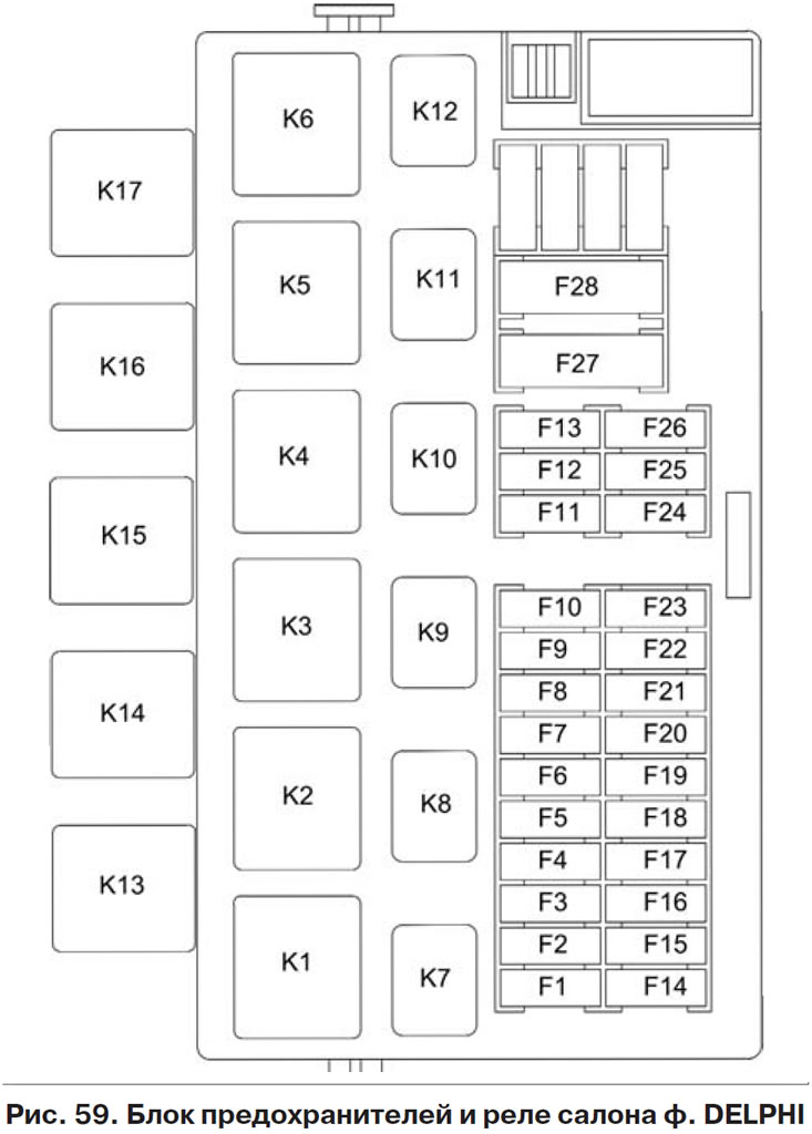
| F31 (for the block before th f. AVAR) / F27 (for the block before th f. Delphi) | 25A | Anti-lock brake system control unit |
| F32 (for the block before th f. AVAR) / F28 (for the block before th f. Delphi) | 30A | Heater fan |
| Climate control system controller |
* A set of fuses is indicated for the maximum configuration of the version «luxury» (depending on the set of options, individual fuses from this set may not be used in other configurations).
** Fuses, the rating of which may vary in different vehicle configurations, depending on the set of options.
Table 5. Electrical circuits protected by fuses located in the fuse box and the interior relay of the vehicle version «standard»
| fuse no | Denomination | Protected circuits |
| F1 | 15A | Ignition coils |
| nozzles | ||
| Engine management system controller | ||
| F2 | 5A | Daytime Running Lights |
| F3 | 10A | Alarm |
| F4 | 15A | Controller of the inflatable airbag system |
| F5 | 7.5A | Terminal 15 devices |
| F6 | 7.5A | reversing light |
| direction indicators | ||
| F7 | 7.5A | Canister purge valve |
| Mass Air Flow Sensor / Pressure Sensor | ||
| F7 | 7.5A | Phase sensor |
| Oxygen concentration sensors | ||
| F8 | 25A | Rear window heater |
| F9 | 5A | Marker lights starboard |
| F10 | 5A | Marker lights, port side |
| Illumination of instruments and keys | ||
| License plate lights | ||
| Trunk light | ||
| Glove box light | ||
| F11 | 5A | Rear fog lights |
| F12 | 10A | Dipped beam, right headlight |
| Right headlight electric corrector | ||
| F13 | 10A | Dipped beam, left headlight |
| Electric corrector of the left headlight | ||
| F14 | 10A | High beam, right headlight |
| F15 | 10A | High beam, left headlight |
| F16 | ||
| F17 | ||
| F18 | 15A | cigarette lighter |
| F19 | 20A | Door lock motors |
| F20 | 15A | Sound signal |
| F21 | 10A | Fuel pump |
| F22 | 15A | Windshield washer |
| windshield wiper | ||
| Rear window washer | ||
| Rear window cleaner | ||
| F23 | 5A | instrument cluster |
| Diagnostic connector | ||
| F24 | ||
| F25 | 7.5A | Brake signals |
| Interior lighting dome | ||
| F26 | ||
| F31 (for the block before th f. AVAR) /F27 (for the block before th f. Delphi) | 30A | Front electric windows |
| F32 (for the block before th f. AVAR) /F28 (for the block before th f. Delphi) | 30A | Heater fan |
Table 6. Relays located in the fuse box and vehicle interior relays «norm» And «luxury» *
| relay no | Denomination | Relay assignment |
| K1 | 30A | Radiator fan relay |
| K2 | 30A | Radiator fan relay |
| K3 | 30A | Additional starter relay |
| K4 | 50A | Ignition Switch Relief Relay |
| K5 | ||
| K6 | 30A | Seat heating relay |
| K7 | 20A | High Beam Relay |
| K8 | 20A | Horn relay |
| K9 | 20A | Relay low beam headlights |
| K10 | 20A | Heated rear window and exterior mirror relay |
| K11 | 20A | ECM main relay |
| K12 | 20A | Fuel pump relay |
| K13 | 30A | Reverse light relay |
| K14 | 30A | Radiator fan relay |
| K15 | 30A | Heated windshield relay |
| K16 | 30A | Heated windshield relay |
| K17 | 30A | A/C compressor clutch relay |
* A set of relays is indicated for the maximum configuration of the version «luxury» (depending on the set of options, individual relays from this set may not be used in other configurations).
Table 7. Relays located in the fuse box and relays for the interior of the car version «standard» *
| relay no | Denomination | Relay assignment |
| K1 | 30A | Radiator fan relay |
| K2 | 30A | Power window relay |
| K3 | 30A | Additional starter relay |
| K4 | 50A | Ignition Switch Relief Relay |
| K5 | Turn signal and alarm relay | |
| K6 | Wiper relay | |
| K7 | 20A | High Beam Relay |
| K8 | 20A | Horn relay |
| K9 | 20A | Relay low beam headlights |
| K10 | 20A | Heated rear window relay |
| K11 | 20A | ECM main relay |
| K12 | 20A | Fuel pump relay |
| K13 | 30A | Alarm relay optional |
| K14 | 30A | Alarm relay optional |
| K15 | ||
| K16 | ||
| K17 |
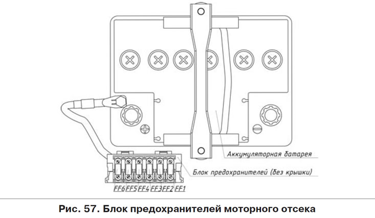
Table 8. Circuits Protected by Fuses in the Engine Compartment Fuse Box*
| fuse no | Denomination | Protected circuits |
| FF1 | 50A | Windscreen heater |
| FF2 | 60A | Generator |
| FF3 | 60A | Generator |
| FF4 | 40A (in the configuration without air conditioning - 30A) | Radiator cooling fans |
| FF5 | 50A | Electromechanical power steering |
| FF6 | 40A | Anti-lock brake system control unit |
* Specified set of fuses for version «luxury». In other versions, individual fuses from this set may not be used.
Attention! Do not use fuses that differ in current rating from those recommended in table 4. This may lead to failure of the vehicle's electrical equipment or a fire.
To access the mounting block with fuses (pic. 56) pull the lower left corner of the cover and release the left locking point 1, then release the middle lower point 2 and the lower right point 3, then release the upper locking points 4, 5 and remove the cover. The cover is installed in the following order: insert the latch 6 into the hole in the instrument panel and, starting from the lower right edge, snap the lower elements of the cover fasteners at points 3, 2, 1, and then the upper ones at points 4 and 5. Make sure that the fasteners fit exactly covers into metal clips mounted on the instrument panel.
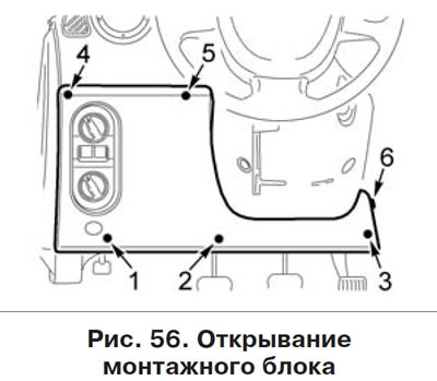
The current strength for which the fuse is designed is indicated on its front part, and the fuse number is indicated on the body of the mounting block.
When reinstalling the fuse box cover, make sure that the wiring harness block is securely connected to the trunk lock actuator switch and that there are no pinched wires.
In the event of a repeated failure of the fuse, to find out and eliminate the causes that caused it to melt, contact a SSSS certified by the manufacturer.