



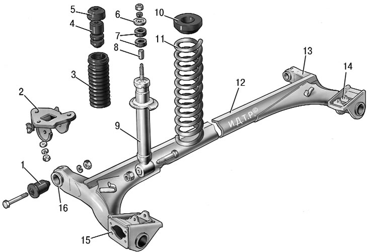
Figure 7.3. Rear suspension parts: 1 – rubber-metal hinge; 2 – suspension arm mounting bracket; 3 – shock absorber casing; 4 – compression stroke buffer; 5 – casing cover; 6 – support washer; 7 – shock absorber cushions; 8 – spacer sleeve; 9 – shock absorber; 10 – insulating gasket; 11 – rear suspension spring; 12 – lever connector; 13 – rear suspension beam arm; 14 – shock absorber mounting bracket; 15 – flange; 16 – lever bushing
The rear suspension beam consists of two longitudinal arms 13 (figure 7.3) and connector 12, which are welded together through reinforcements.
At the rear, brackets 14 with lugs for attaching shock absorbers and flanges 15 are welded to the suspension arms, to which the rear wheel axles are bolted together with the wheel brake shields. At the front, bushings 16 are welded to the suspension arms, into which rubber-metal hinges 1 are pressed. Bolts pass through the hinges, connecting the suspension arms with stamped-welded brackets 2, which are attached to the body side members with welded bolts.
The springs 11 of the suspension rest with one end on the cup of the shock absorber 9, and with the other end through the rubber insulating gasket 10 in the support welded to the inner arch of the body.
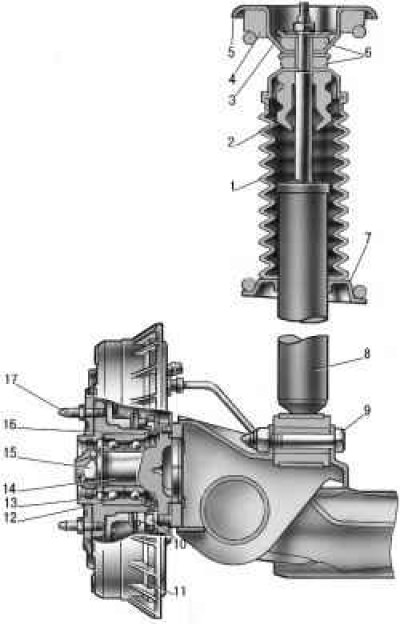
Figure 7.4. Shock absorber mounting: 1 – protective cover; 2 – compression stroke buffer; 3 – support washer; 4 – spring insulating gasket; 5 – upper support cup of the suspension spring; 6 – shock absorber rod mounting cushions; 7 – lower spring support cup; 8 – shock absorber; 9 – shock absorber mounting bolt; 10 – wheel hub axle mounting bolt; 11 – brake drum; 12 – hub bearing; 13 – wheel hub; 14 – axis; 15 – nut; 16 – retaining ring; 17 – mounting pin
The rear suspension shock absorber is hydraulic, telescopic, double-acting. It is attached with a 9 bolt (figure 7.4) to the suspension trailing arm bracket. The rod is attached to the upper support 5 of the suspension spring through rubber cushions 6 and a support washer 3.
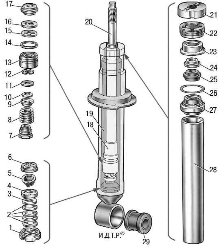
Figure 7.5. Rear suspension shock absorber parts: 1 – compression valve body; 2 – compression valve discs; 3 – compression valve throttle disc; 4 – compression valve plate; 5 – intake valve spring; 6 – compression valve holder; 7 – recoil valve nut; 8 – recoil valve spring; 9 – recoil valve plate; 10 – washer; 11 – recoil valve disc; 12 – throttle disc of the return valve; 13 – piston; 14 – piston ring; 15 – bypass valve plate; 16 – bypass valve spring; 17 – limiting plate; 18 – spacer sleeve; 19 – reservoir; 20 – rod; 21 – compression buffer support; 22 – nut; 23 – oil seal cage; 24 – Protective ring of the rod; 25 – oil seal; 26 – reservoir sealing ring; 27 – rod guide bushing; 28 – cylinder; 29 – rubber-metal hinge
The shock absorber parts are shown in the figure 7.5.
In the hub 13 (see figure 7.4) a double-row radial thrust bearing 12 is installed, similar to the front wheel hub bearing, but smaller in size. Unlike the front wheel hub, on which the inner bearing ring is installed with a guaranteed tension, on the rear wheel hub, bearing 12 on axle 14 has a transition fit.