



Checking the air pressure in the tires
The vehicle must be equipped with tires of the same model and with the same markings.
When installing tires with a directional tread pattern, which can be identified by the arrow on the sidewalls, it is necessary to check that the arrows match the direction of rotation of the wheels.
Check the air pressure in the tires, including the spare tire, and if necessary, bring it up to the standard in accordance with Table 3.
Table 3
| Modification and execution of the car | Tire dimensions with load capacity and speed indexes* | Wheel dimensions | Air pressure in tires front/rear, MPa (kgf/cm²) | |||
| Rim width (inches | Rim offset (ET)**, mm | partial load*** | full load**** | |||
| Set by the manufacturer | ||||||
| hatchback version) | All modifications | 195/65R15 91N 205/55R16 91H | 6J 6J | 37-40 41 | 0,22/0,20 (2,2/2,0) | 0,22/0,20 (2,2/2,0) |
| Allowed to be installed during operation | ||||||
| hatchback version) | All modifications | 195/65R15 91T. H. V 205/55R16 91T, H, V | 6J 5/J, 6J, 6/J | 37-40 41 | 0,22/0,20 (2,2/2,0) | 0,22/0,20 (2,2/2,0) |
* Speed indices: T - up to 190 km/h, H - up to 210 km/h, V - up to 240 km/h. Load capacity indices: 91-615 kg.
** Rim offset (ET) is the distance from the mating plane of the disc to the center of the rim.
*** Partial load - no more than 3 adults in a car without cargo in the trunk.
**** Full load - more than 3 adults or 3 adults and 50 kg of cargo in the trunk.
It is permitted to use winter tires (M+S) of the above dimensions and index Q with the corresponding maximum vehicle speed limitation (up to 160 km/h).
Tears and swelling of the sidewalls are not allowed.
Checking the headlight beam direction and headlight beam aiming system
Check the operation of the headlight beam adjuster.
The check is performed with the corrector in the position corresponding to the minimum load of the vehicle.
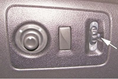
Figure 13 - Checking the operation of the headlight range control switch.
The adjustment of the low beam headlights should be performed by turning the handle (figure 13) to align one of the marks on the switch wheel scale corresponding to the vehicle loading state with the mark on the housing:
- 0 - driver or driver + front passenger;
- 1 - driver + cargo in the luggage compartment;
- 2 - driver + 4 passengers;
- 3 - driver + 4 passengers + cargo in the luggage compartment.
The test must be carried out in accordance with the requirements of TI 3100.25100.13054.
Checking the operation of lighting devices, cigarette lighter, light and sound signaling
Install the cigarette lighter movable element (if available) and check its operation, the operation of electrical equipment, light and sound alarms, switches and switches.
Headlights, direction indicators, hazard warning lights, brake lights, side lights, daytime running lights, fog lights, rear lights with lamps for the appropriate purpose, control devices and instrument cluster lighting, cigarette lighter, as well as devices and mechanisms for switching on, off and adjusting must be in good working order and in good working order.
Checking the operation of the windshield wiper and washer
Check the operation of the windshield washer and wiper. The windshield wiper must work in all modes. The windshield washer pump must supply washer fluid to the upper part of the working area of the wipers. The brushes must be positioned horizontally in one line and must not touch the glass edge during operation (spanner 16).
The frequency of movement of the windshield wiper blades on wet glass at the minimum rotation speed of the engine crankshaft is not less than 35 double strokes per minute.
Checking the operation of the rear window heater and front seat heater
Operation of the rear window heater and front seat heating system (if available) check by turning on the control lamps.
Checking the operation of door, hood, and tailgate locks
Check the operation of the locks on the front doors, rear doors, hood, tailgate, and adjust if necessary. The doors, hood and tailgate should open and close easily without much force and should lock in the open position. Spontaneous opening is not allowed.
Adjusting the operation of the side door locks (figures 14 and 15) to produce by moving the retainer relative to the body pillar (phillips screwdriver, replaceable TORX T40 head, ratchet).
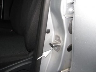
Figure 14 - Adjusting the front lock
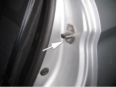
Figure 15 - Adjusting the rear door lock
Adjusting the operation of the hood lock (figure 16) produced by moving the lock body relative to the radiator frame (spanner 13).
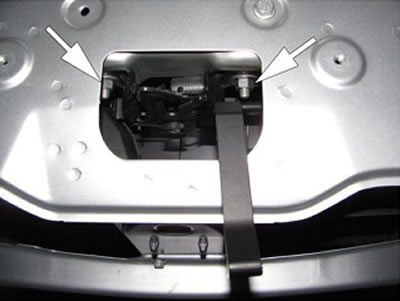
Figure 16 - Adjusting the hood lock
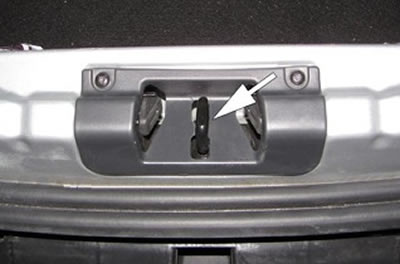
Figure 17 - Adjusting the tailgate lock
Adjust the operation of the tailgate lock by moving its latch (figure 17) (tORX T40 replaceable head, ratchet). The gaps between mating body parts must comply with the requirements of TU 017207-255-00232934-2006.
Checking the operation of the electric window lifts and outside mirrors
The window lifters should operate smoothly, without sticking. Skewing of glass in openings and spontaneous movement of glass are not permitted.
For vehicles equipped with electric windows and electric exterior mirrors, check their functionality. The control unit for the window lifters and the drive of the outside mirrors must ensure smooth, jam-free operation of the window lifters and adjustment of the outside mirrors (figure 20).
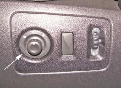
Figure 20 - Checking the operation of the outside rearview mirror adjustment switch.
Checking the operation of seat belts
Check the operation of the seat belts. Lock (figure 21) must securely fix the belt. The tape must not have any breaks or twists. When the tongue is properly locked in the lock, a characteristic click should be heard. The tape pulled out of the reel should be pulled back into place by itself under the action of the return spring.
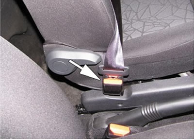
Figure 21 - Checking the operation of the seat belt buckle
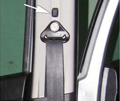
Figure 22 - Checking the movement of the seat belt adjuster
When you press the key (figure 22), the seat belt adjuster should move downwards, and the adjuster should move upwards without pressing the button.
Checking the steering column movement
Check the movement and fixation of the steering column (figure 23). With the adjustment lever down, the steering column should move smoothly, without jerking or jamming, up and down and forward and backward. With the adjustment lever up, the steering column should be securely fixed in the set position.
Caution: Adjust the steering column position only when the vehicle is stationary.
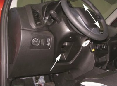
Figure 23 - Checking the movement and fixation of the steering column
Checking the operation of the front seat adjustment mechanisms
With the locking lever raised (figure 24), the seat should move smoothly, without jamming, in the longitudinal direction; when the mechanism is locked, the seat cannot be moved. Blocking should be carried out in any (between two extremes) fixed seat position.
Caution: Do not adjust the driver's seat while the vehicle is moving.
Check the operation of the front seat backrest tilt adjustment mechanism (figure 25). When the adjustment handle is raised, the seat back should smoothly, without jamming, change its position and be securely fixed in the set position.
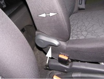
Figure 25 - Checking the operation of the front seat backrest tilt mechanism
Check the operation of the seat height adjustment mechanism (figure 26). When the lever is raised or lowered, the angle and position of the seat cushion should be adjusted, the seat cushion should rise or fall.
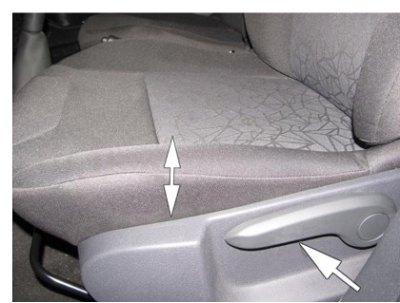
Figure 26 - Checking the operation of the seat height adjustment mechanism
Check the operation of the headrest movement and removal mechanism (figure 27). The headrest should move smoothly upward in the seat back guides and be held in fixed height positions. When the locking button on the support is pressed, the headrest should move down to the required position, and also be removed from the seat back and installed in place.
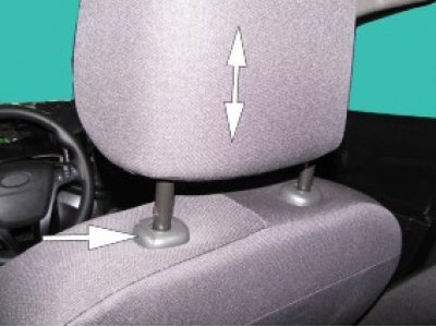
Figure 27 - Checking the movement and fixation of the headrest
Check the operation of the rear seat back folding mechanism. When you pull the release handle up, the rear seat back should fold.
Checking the operation of the fuel tank hatch cover and the reliability of the fuel tank filler cap fixation
Spontaneous opening of the fuel tank hatch cover is not permitted.
Unscrew and then screw in the fuel tank filler cap (figure 29). The plug must be securely fixed in the closed position; damage to the sealing element of the plug must not be allowed.
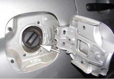
Figure 29 - Checking the reliability of the fuel tank filler cap fixation