



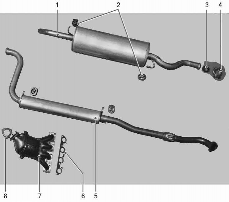
Pic. 5.24. Exhaust system: 1 - main muffler; 2 - suspension cushions of the main and additional mufflers; 3 - sealing ring; 4 - collar; 5 – additional muffler; 6 - exhaust manifold gasket; 7 - exhaust manifold with converter assy (collector); 8 – laying of a reception pipe of the additional muffler
Exhaust gases are removed from the engine through the exhaust manifold 7 (pic. 5.24), combined with neutralizer (collector), additional muffler 5 and main muffler 1.
Two oxygen sensors are installed on the collector 7: diagnostic and main (manager).
A sealing metal-reinforced gasket 6 is installed between the cylinder head and the exhaust manifold flange. A toroidal metal-graphite ring 3 is installed between the flanges of the muffler pipes forming a hinge, and the inner spherical surfaces are made in the flanges.
To reduce the transmission of vibrations from the power unit to the exhaust system and the body, a vibration-compensating corrugated bellows in a metal braid is mounted in the exhaust pipe of the additional silencer.
The collector 7 is fixed with nuts on the studs of the cylinder head and is additionally fixed to the engine with a bracket.
The elements of the system are suspended from the body on four rubber cushions 2.
To protect the engine and the base of the body from heating by the elements of the system, steel thermal screens are installed in front of the collector and above the additional muffler. In addition to them, an additional heat-insulating shield is installed in the engine compartment, which protects the steering mechanism from overheating (in fig. 5.24 thermal shields not shown).
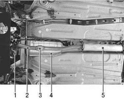
Pic. 5.25. The location of the elements of the exhaust system in the front of the car: 1 - collector; 2 – a reception pipe of an additional muffler; 3 - bellows; 4 - front thermal screen of the additional muffler; 5 - additional muffler
The arrangement of elements of system on the car is shown in fig. 5.25 and 5.26.
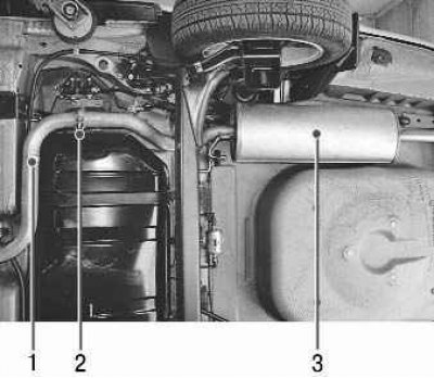
Pic. 5.26. The location of the elements of the exhaust system in the rear of the car: 1 – an exhaust pipe of the additional muffler; 2 - movable hinge; 3 - main muffler
The exhaust system does not require special maintenance. It is enough to periodically check the reliability of the tightening of the threaded connections and the integrity of the suspension pads. In case of damage to the elements of the system, through corrosion or burnout, they are replaced as an assembly, since the mufflers, together with the pipes, are non-separable units.
Note. Periodically check the exhaust system. If there is an increased noise level from the exhaust system, check its tightness. To do this, start the engine and inspect the entire system. By running your hand over the places of a possible leak, without touching the nodes, you will immediately feel the leakage of gases. If necessary, replace rusted and burnt parts.
Attention! Allow the exhaust system to cool before repairing the exhaust system, as the exhaust system becomes very hot when the engine is running.
Warning! Exhaust gases are poisonous, their poisoning occurs imperceptibly, so be sure to open the gate before starting the engine in the garage!
To remove and install system components, you will need: keys «on 10», «at 13», «at 17», pliers with narrow jaws, a screwdriver with a flat blade.