
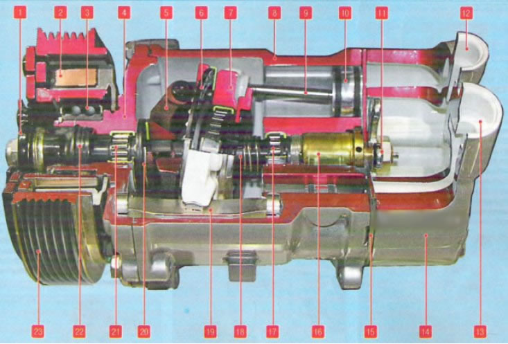
Air conditioning compressor: 1 - pressure disk; 2 - electromagnet winding; 3 - pulley bearing; 4 - front cover of the case; 5 - swash plate clip lever; b - swashplate thrust roller bearing; 7 - inclined washer; 8 - compressor housing; 9 - connecting rod; 10 - piston; 11 - nut for fastening the block of valves of the regulator and stops of the block of petal valves; 12 - fitting of the injection line; 13 - suction line fitting; 14 - valve block cover; 15 - block of petal valves; 16 - block of valves of the performance regulator; 17.21 - shaft bearings; 18 - swashplate shaft; 19 - swashplate guide stop; 20 - shaft thrust bearing; 22 - shaft seal; 23 - drive pulley
Compressor part number see here.
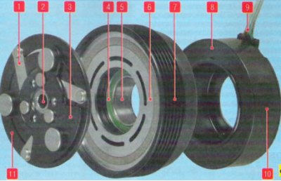
Compressor drive electromagnetic clutch: 1 - elastic steel leash; 2 - slotted hole of the disc hub; 3 - clutch driven disk; 4 - bearing; 5 - inner race of the bearing; b - working surface of the pulley; 7 - pulley streams; 8 - electromagnet winding; 9 - electromagnet wiring harness; 10 - body of the electromagnet; 11 - clutch pressure plate
Removing
Place the vehicle on a two-post lift, brake with the parking brake and disconnect the wire terminal "masses" from battery (wrench "on 10").
Drain the refrigerant from the vehicle's air conditioning system.
Raise the vehicle to a height that is comfortable for the job.
Remove the front right wheel.
Remove the right mud guard and the right wheel arch protective cover.
Attention. Do not turn the engine crankshaft in the opposite direction to the direction of rotation.
Attention. Do not start the engine without the accessory drive belt, as this may damage the crankshaft pulley.
Attention. Do not damage the air conditioning pipes.
Remove the accessory drive belt as instructed in this manual.
Attention. The removed accessory drive belt must be replaced.
Loosen two bolts 4, Figure 5-6, fastening pipelines. Disconnect line 1 connecting the compressor to the condenser and line 2 connecting the compressor to the evaporator (long part) from the compressor (interchangeable head 13, knob and extension). Install technological plugs on the pipelines and in the openings of the compressor.
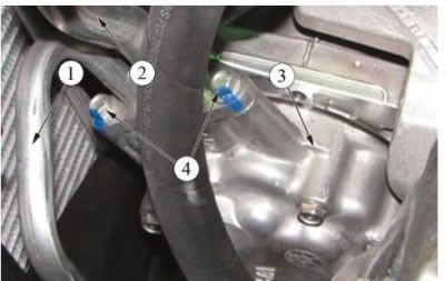
Figure 5-6 - Removing the compressor piping: 1 - pipeline connecting the compressor with the condenser; 2 - pipeline connecting the compressor with the evaporator (long part); 3 - compressor; 4 - pipeline fastening bolts
Disconnect connector 3, Figure 5-7, compressor solenoid clutch 1 from vehicle wiring harness (flat screwdriver).
Unscrew the four bolts 2, Figure 5-7, fastening the compressor 1 to the bracket, remove the bolts 2 and remove the compressor 1 (interchangeable head 13, knob and extension).
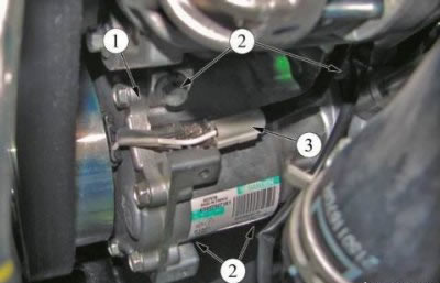
Figure 5-7 - Removing the compressor: 1 - compressor; 2 - compressor fastening bolts; 3 - plug
Installation
Align the holes in the lugs of the compressor 1, Figure 5-7, and in the bracket and install four bolts 2 of the compressor 1 into the holes. The tightening torque of the compressor mounting bolts is 21 Nm (2.1 kgf·m) (interchangeable head 13, knob, extension, torque wrench).
Remove plugs from compressor 3, Figure 5-6, and lines 1 and 2. Install new O-rings before installing lines 1 and 2. Apply Sanden SP-10 compressor oil to the O-rings and connect the pipelines to the compressor. The moment of an inhaling of bolts 4 fastenings of pipelines 1 and 2 compressors - 8 Nm (0.8 kgf·m) (interchangeable head 13, knob and extension, torque wrench).
Install the accessory drive belt.
Connect connector 3, Figure 5-8, compressor solenoid clutch 1 to vehicle wiring harness (flat screwdriver).
Install and secure the right mudguard.
Evacuate the air conditioning system and charge the system with refrigerant (refrigerant R134a, loading rate - 475±35 g).
Check the air conditioning system for refrigerant leaks (leak detector).
Check the operation of the air conditioning system.