



To complete the work you will need a multimeter.
Removal
1. Prepare the car for work and disconnect the wire terminal from the negative terminal of the battery ("Preparing the car for maintenance and repair").
2. Press the clamps of the wiring harness connector and disconnect the connector from the gas pedal sensor.
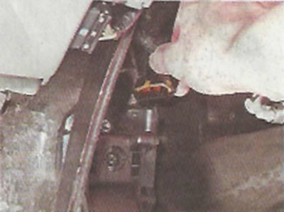
3. Using a 10 mm socket wrench, unscrew the three nuts securing the gas pedal.
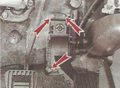
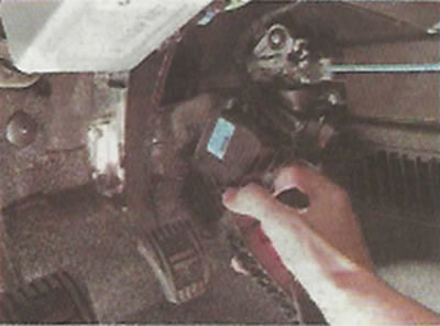
4. Remove the pedal from the studs.
Examination
Using a multimeter in ohmmeter mode, you can check the condition of the moving contacts and conductive tracks of the gas pedal position sensors. To do this:
1. Connect one probe of the multimeter to terminal 4 and the other to terminal 2.
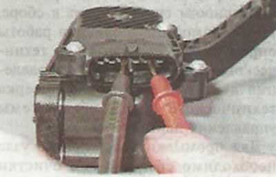
Note: For ease of testing, you can put pieces of PVC tubes on the terminals and insert the multimeter probes into them.
2. Slowly moving the gas pedal, we check the electrical resistance on the instrument, which should gradually decrease.
3. Repeat the test by connecting the multimeter to terminals 4 and 3.
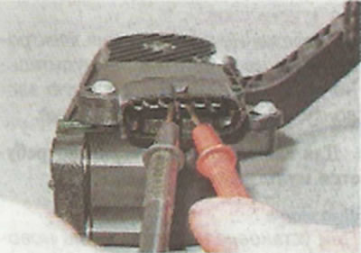
4. Similarly, we check the conductive path of the other sensor, sequentially connecting the multimeter to terminals 1-6 and 6-5.
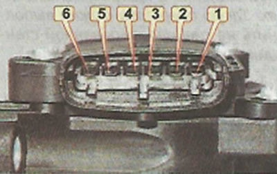
If the resistance changes abruptly when checking any of the tracks, the sensor should be replaced.
Installation
We install the gas pedal in the reverse order. To avoid accidentally bending the terminals in the gas pedal sensor connector, connect the wiring block before installation. Then we put the gas pedal bracket on the studs. Tighten the pedal mounting nuts to a torque of 6-8 Nm.
Table 8.2.3. Electronic gas pedal pin assignments
| Output number | Electronic gas pedal circuit | Purpose of the output |
| 1 | Sensor #2 | Supply voltage (+3.3 V) |
| 2 | Sensor No. 1 | Supply voltage (+3.3 V) |
| 3 | "Weight" | |
| 4 | Signal from sensor #1 | |
| 5 | Sensor #2 | "Weight" |
| 6 | Signal from sensor #2 |