



Install pin 4 of the crankshaft position setting disk on crankshaft 1, Figure 34, setting disk 2, screw in and tighten three bolts 3 of the setting disk fastening. Tightening torque of the disc mounting bolts is 20...24 N·m (2.0...2.4 kgf·m). Remove the centering pin from the crankshaft (centering pin 12313ED000, replaceable head TORX T40, ratchet, extension, torque wrench).
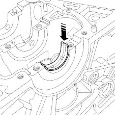
Figure 34 - Installing the crankshaft position setting disk: 1 - crankshaft; 2 - crankshaft position setting disk; 3 - bolts for fastening the timing disk; 4 - centering pin 12313ED000
Select crankshaft main bearing shells according to the classification of crankshaft main journals and bearings in the cylinder block in accordance with Table 7.
The color in the table indicates the marking of the insert applied to its end. The color of the marking corresponds to a specific class of the liner, which must be installed depending on the class of the diameter of the main journals and the class of the diameter of the holes in the supports.
The upper part of the table shows the classes of bore diameters in the cylinder block supports, and the left part shows the classes of crankshaft main journal diameters.
Abbreviations given in Table 6:
- UPR - liner installed in the cylinder block support;
- LWR - a liner installed in the main bearing cap.
Install the grooved liners into the cylinder block bearings. Align the new bearing shells with the grooves in the cylinder block, aligning the groove in the shell with the groove in the support.
Position the bearing shell flush with the support as shown in Figure 35 and press down on it from the back side to position the shell flush with the support.
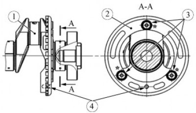
Figure 35 - Installing the main bearing shell into the cylinder block
Repeat the operation for the remaining inserts.
Adjust the position of the liners so that they are located in the center of the cylinder block supports.
Install the liners without grooves into the cylinder block covers.
Position the bearing shell flush with the main bearing cap surface as shown in Figure 36 and slide it to the opposite side until it is aligned with the cap.
Repeat the operation for the remaining inserts.
Adjust the position of the liners so that they are located in the center of the cylinder block covers.
Install the crankshaft thrust half rings in the sockets of the third support of the cylinder block, aligning the antennae of the half rings with the grooves 1, Figure 37, of the support. In this case, the grooves 2 of the half rings should be on the crankshaft side.
Lubricate the surfaces of the main bearing shells and the crankshaft thrust half rings that come into contact with the crankshaft with engine oil (engine oil according to Appendix A of the current "Consumption standards for main and auxiliary materials for maintenance and repair of LADA vehicles").
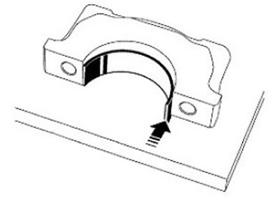
Figure 36 - Installing liners in main bearing caps
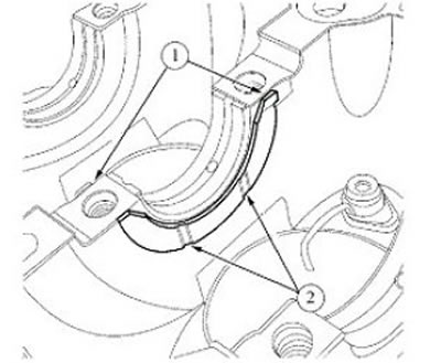
Figure 37 - Installing thrust half rings: 1 - grooves in the crankshaft support; 2 - grooves on thrust half rings
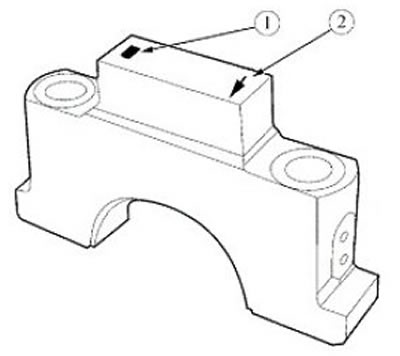
Figure 38 - Marking of main bearing caps: 1 - place of application of the cover number; 2 - installation mark (arrow)
Install the crankshaft into the cylinder block
Install the main bearing caps with liners onto the cylinder block in accordance with their numbering. The numbering of the covers starts from the timing drive side. The arrows on the covers should point towards the timing drive. The numbering and arrows are located on the surfaces of the cover bosses, as shown in Figure 38.
Install and tighten new main bearing cap bolts.
Tighten the main bearing cap bolts in two steps (tORX E14 replaceable head, ratchet, extension, torque wrench, angle measuring head):
- tighten the bolts to a tightening torque of 30...35 N·m (3.0...3.5 kgf·m);
- tighten the bolts to an angle of 60°...65°.
Check the crankshaft rotation. The shaft should rotate freely and without jamming with the force of your hand. If rotation is difficult or there is jamming, it is necessary to remove the crankshaft and repeat the operation to select a set of liners.
Check the crankshaft axial clearance. Install a stand with an indicator on the cylinder block, as shown in Figure 39. Rest the measuring rod of the indicator on the crankshaft flange and set the indicator scale to zero. By moving the crankshaft with screwdrivers, measure the axial clearance of the shaft. The axial clearance of the crankshaft should be within 0.1_0.3 mm. If the axial clearance is more than 0.3 mm, adjust the clearance by replacing the thrust half rings (tripod SHM-PV-8, indicator ICH-10, flat screwdriver - 2 pcs., micrometer type MK 25-1).
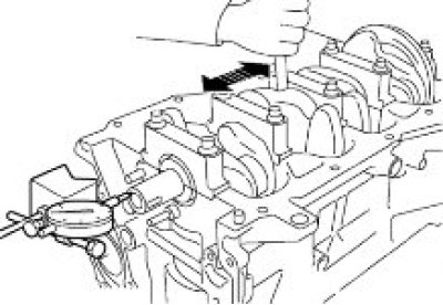
Figure 39 - Checking the crankshaft axial clearance
Check the height clearances between the piston grooves and rings and the clearances in the ring joints. The gap between ring 1, Figure 40, and the wall of the piston groove 2 for the upper compression ring should be 0.06...0.15 mm, for the second - 0.03...0.07 mm, for the oil scraper ring - 0.045...0.125 mm. The gap is measured at three points located at an angle of 120° to each other.
The gap in the lock of the upper compression ring should be 0.2...0.3 mm, for the second - 0.35...0.50 mm, for the oil scraper ring - 0.20...0.45 mm. Piston rings with a gap in the lock exceeding the maximum value should be replaced, if the gap is less than the minimum value, it is permissible to file the mating surfaces of the ring (set of feeler gauges, file).
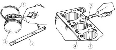
Figure 40 - Checking piston ring clearances: 1 - piston ring; 2 - piston; 3, 5 - feeler gauges; 4 - cylinder block