



Unscrew the oil drain plug, drain the oil from the engine and screw in the plug (replaceable head 15, ratchet, installation type 24164 f. "ALFA" (Italy) for collecting used oil).
Loosen the tightening of bolts 1, Fig. 4, of the water pump pulley, blocking the water pump pulley with a screwdriver.
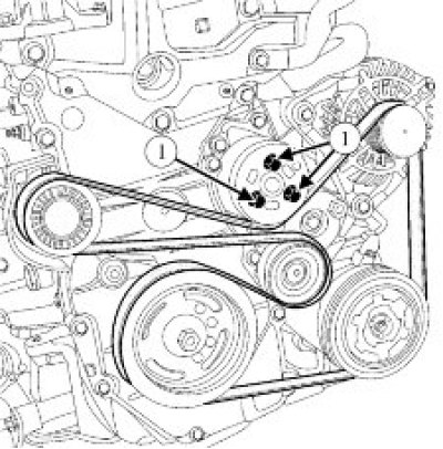
Figure 4 - Removing the water pump pulley: 1 - water pump mounting bolts
Remove the accessory drive belt.
Loosen the water pump pulley mounting bolts while holding the pulley with a screwdriver and remove the pulley (flat head screwdriver, replaceable head 10, ratchet).
Disconnect the heating hoses from the throttle body (pliers).
Disconnect the throttle body heating hoses from the coolant outlet pipe and remove the hoses from the engine (pliers).
Remove the crankcase ventilation tube (pliers).
Remove the intake module assembly with the throttle body and gaskets (replacement head 10, ratchet, extension).
Remove the wiring harness mounting bracket (replaceable head 8, ratchet).
Remove the fuel rail protective screen (replaceable heads 8, 10, extension, ratchet).
Disconnect the ignition coil wiring harness connectors from the ignition coils.
Disconnect the injector wiring harness connectors from the fuel injectors and remove the harness from the engine.
Remove the fuel rail with injectors assembly (replacement head 10, ratchet, extension).
Remove the ignition coils (replaceable head 8, ratchet and extension).
Remove the spark plugs (14 key for spark plugs).
Loosen the mounting bolt and remove the phase sensor (replacement head 10, ratchet and extension).
Loosen the mounting bolt and remove the electromagnetic valve of the phase regulator (replaceable head 8, ratchet and extension).
Remove the oil level indicator tube (grab grip (pincers)).
Loosen the mounting bolts and remove the cylinder head cover (replaceable head 8, ratchet and extension).
Turn the crankshaft clockwise until mark 1, Figure 5, on the crankshaft pulley and mark 2 on the timing cover are aligned. The marks on the camshaft phase regulator 1 and the exhaust camshaft sprocket 2 are positioned as shown in Figure 6. Otherwise, turn the crankshaft one more revolution until the marks on the crankshaft pulley and on the timing cover are aligned.
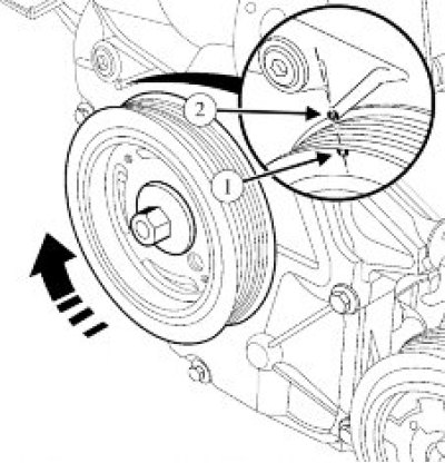
Figure 5 - Setting TDC: 1 - mark on the crankshaft pulley; 2 - mark on the timing belt cover
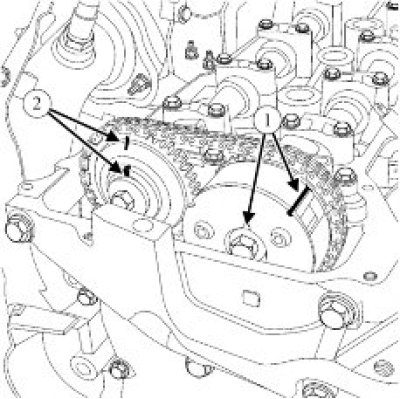
Figure 6 - Checking the marks in the timing drive mechanism: 1 - camshaft phase regulator marks; 2 - camshaft sprocket marks
Install retainer 1, Fig. 7, of the flywheel (flywheel lock 67.7820-9708 or 00 00 143 100).
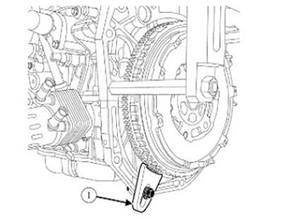
Figure 7 - Installing the flywheel lock: 1 - flywheel lock
Loosen the mounting bolt and remove the crankshaft pulley (replaceable head 19, ratchet).
Remove the front crankshaft oil seal as shown in Figure 8 (flat screwdriver, wooden or plywood thrust plate).
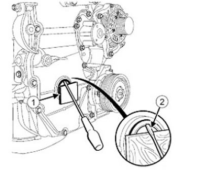
Figure 8 - Removing the front crankshaft oil seal: 1 - thrust plate; 2 - flat screwdriver
Loosen the mounting bolts and remove the flywheel and flywheel retainer (replaceable head TORX E20. ratchet).
Remove the rear crankshaft oil seal as shown in Figure 9 (flat head screwdriver).
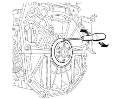
Figure 9 - Removing the rear crankshaft oil seal
Loosen the timing belt cover mounting bolts (replaceable heads 8, 10, 13, ratchet).
Carefully remove the timing belt cover as shown in Figure 10.
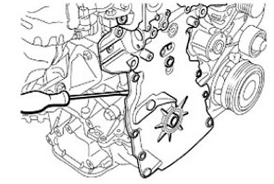
Figure 10 - Removing the timing belt cover
Disconnect the timing belt cover as shown in Figure 11, remove the cover (tool 67.7812-9712 for removing the crankcase or 77 11 381 716. hammer with plastic striker).
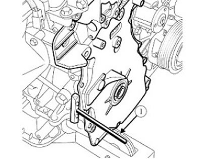
Figure 11 - Removing the timing belt cover: 1 - tool 67.7812-9712 for removing the crankcase or 77 11 381 716
Check the position of links 1, Figure 12, of the timing chain relative to marks 2 on the crankshaft sprocket, camshaft sprocket and phase regulator. The difference in the position of the chain links relative to all three marks must be the same.
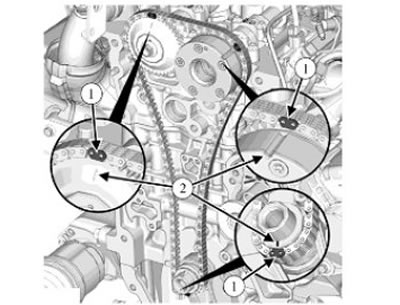
Figure 12 - Checking the position of the chain links: 1 - chain links; 2 - marks on the crankshaft sprocket, on the camshaft sprocket and on the phase regulator
Press the chain tensioner plunger into the tensioner housing by pressing on shoe 1, Figure 13.
Fix the plunger by installing a piece of steel wire 2 with a diameter of 2.5 mm into the hole in the tensioner housing.
Loosen the tensioner mounting bolts and remove the tensioner, making sure not to release the plunger (replaceable head 8, ratchet).
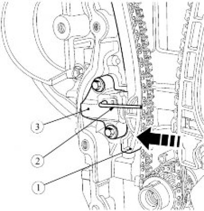
Figure 13 - Removing the hydraulic timing chain tensioner: 1 - tensioner shoe; 2 - retainer (steel wire); 3 - hydraulic tensioner
Remove the timing chain tensioner shoe.
Loosen the mounting bolts and remove the timing chain guide (replacement head 10, ratchet).
Remove the timing chain from the engine.
Turn tensioner 1, Fig. 14, of the oil pump drive chain counterclockwise.
Remove the oil pump drive chain tensioner from the shaft and tensioner spring 2 from the cylinder block.
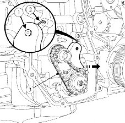
Figure 14 - Removing the oil pump drive chain tensioner: 1 - oil pump drive chain tensioner; 2 - tensioner spring; 3 - oil pump drive chain
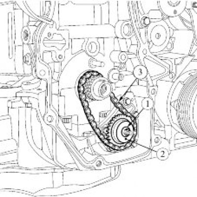
Figure 15 - Removing the oil pump drive chain: 1 - oil pump drive sprocket fastening nut; 2 - oil pump drive sprocket; 3 - oil pump drive chain
Unscrew nut 1, Fig. 15, of the oil pump drive sprocket (ring spanner 10, replaceable head TORX E8, ratchet).
Remove sprocket 2 of the oil pump drive with chain 3 of the pump as an assembly.
Remove the crankshaft sprocket (universal puller).
Loosen the three mounting bolts and remove the oil pump from the cylinder block (replacement head 10, ratchet and extension).
Loosen the four water pump mounting bolts, remove the water pump and gasket (replacement head 10, ratchet).
Loosen the two generator mounting bolts and remove the generator from the engine (replacement head 10, ratchet).
Loosen the three air conditioning compressor mounting bolts and remove the compressor from the engine (replacement head 10, ratchet).
Loosen the four bolts securing the accessory bracket and remove the bracket (replacement head 10, ratchet).
Unscrew the two bolts 1, Fig. 16, securing the thermostat cover, remove the clip securing the oil level indicator tube, cover 2 of the thermostat and remove the thermostat valve from the cylinder block (replacement head 12, ratchet and extension).
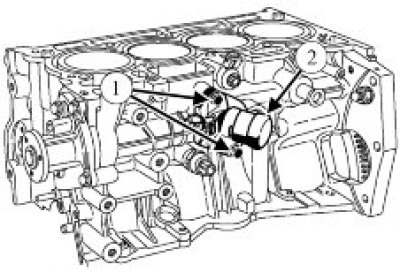
Figure 16 - Removing the thermostat: 1 - thermostat cover mounting bolts; 2 - thermostat cover
Unscrew bolt 1, figure 17, securing the detonation sensor and remove sensor 2 (replacement head 10, ratchet).
Unscrew the oil pressure sensor 3 from the cylinder block (ring spanner 22).
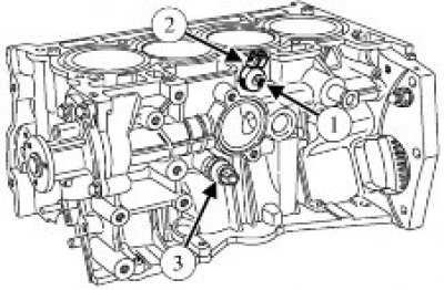
Figure 17 - Removing the knock and oil pressure sensors: 1 - knock sensor mounting bolt; 2 - knock sensor; 3 - oil pressure sensor
Remove the oil filter 1 from the engine, Figure 18 (chain or strap wrench for removing oil filter).
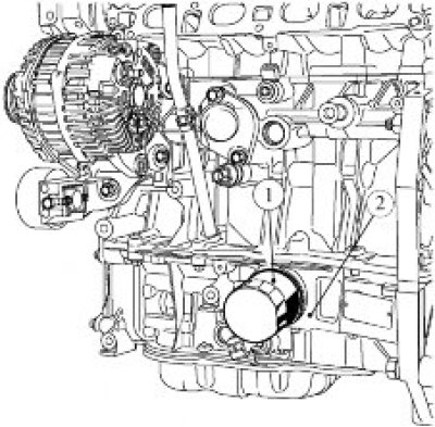
Figure 18 - Removing the oil filter: 1 - oil filter; 2 - cylinder block amplifier
Unscrew the coolant temperature sensor from the coolant outlet pipe (ring spanner 19).
Unscrew the seven bolts securing the coolant outlet pipe, remove the pipe and gasket (replacement head 10, ratchet and extension).
Loosen the crankshaft position sensor mounting bolt and remove the sensor (replacement head 10, ratchet and extension).
Loosen the bolts securing the heat shield of the upper exhaust manifold and remove the shield (replacement head 10, ratchet and extension).
Remove the oxygen sensor from the exhaust manifold (ring spanner 22).
Unscrew the five exhaust manifold mounting nuts, remove the manifold and gasket (replacement head 10, ratchet and extension).
Loosen the bolts securing the heat shield of the lower exhaust manifold and disconnect the shield from the manifold (replacement head 10, ratchet and extension).
Loosen the bolts securing the phase regulator and the camshaft sprocket, holding the camshafts with a wrench, remove the phase regulator 1, Figure 19, and sprocket 2 (22 mm spanner, 13 mm replaceable head, ratchet and extension).
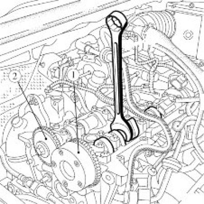
Figure 19 - Removing the phase regulator and camshaft sprocket: 1 - intake camshaft phase regulator; 2 - camshaft sprocket
Loosen the nineteen camshaft bearing cap mounting bolts and remove the caps (replaceable head 8, ratchet).
Remove the camshafts.
Loosen the ten cylinder head mounting bolts, remove the washers, cylinder head and gasket (replacement head 10 for internal hexagon, ratchet and extension).
Loosen the eight bolts securing the oil pan cover and remove cover 1, Figure 20 (replaceable head 8, ratchet, extension, device 67.7812-9712 for removing the crankcase or 77 11 381 716, hammer with plastic striker).
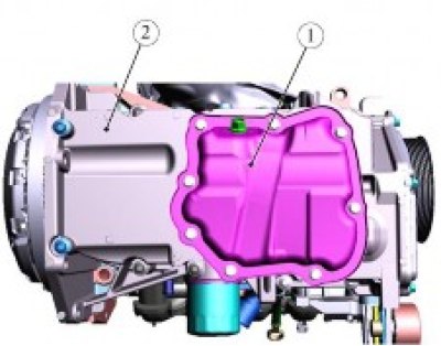
Figure 20 - Removing the oil pan cover: 1 - oil pan cover; 2 - cylinder block amplifier
Loosen the ten cylinder block reinforcement mounting bolts (replacement head 10, ratchet and extension).
Carefully separate the cylinder block amplifier with a screwdriver, as shown in Figure 21a, at points 1 and 2, Figure 21b (flat head screwdriver).
Disconnect the booster 1, Fig. 22, from the cylinder block using tool 2 (tool 67.7812-9712 or 77 11 381 716 for removing the crankcase, hammer with plastic striker).
Remove the sealing ring from the cylinder block.
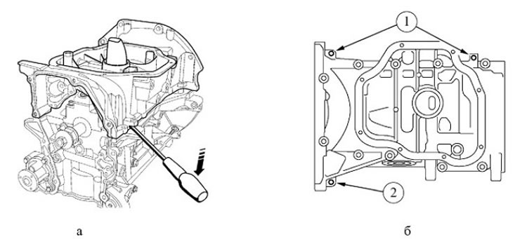
Figure 21 - Removing the cylinder block amplifier
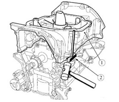
Figure 22 - Removing the cylinder block amplifier: 1 - cylinder block amplifier; 2 - tool 67.7812-9712 or 77 11 381 716 for removing the crankcase
Loosen the connecting rod cap mounting bolts and remove the caps (replacement head 11, ratchet and extension).
Remove the pistons with connecting rods from the cylinder block on the cylinder head installation side.
Caution: When removing the pistons, avoid damaging the lubrication nozzles.
Loosen the crankshaft main bearing cap mounting bolts, remove the caps, crankshaft and thrust half rings (tORX E14 replaceable head, ratchet and extension).
Note: When removing the thrust half rings, mark their position relative to the cylinder block in any way that does not cause damage to the parts.
Loosen the three crankshaft position setting disk mounting bolts and remove the disk (tORX T40 replaceable head, ratchet and extension).