



Inspect engine parts
Not allowed: cracks, breaks, dents, nicks, crushed edges, thread damage of more than two turns, presence of traces of wear and work hardening on the teeth of the sprockets (visual inspection).
The parts whose technical condition does not meet the requirements of this manual, as well as all sealing parts, accessory drive belt, timing chain, timing chain tensioner, timing chain tensioner shoe, timing chain damper, cylinder head gasket, cylinder head mounting bolts, camshaft phase regulator filter, crankshaft pulley mounting bolt, exhaust manifold mounting stud nuts, exhaust manifold mounting studs, oil filter, flywheel mounting bolts, connecting rod cap mounting bolts, crankshaft main bearing cap bolts, crankshaft main bearing shells, connecting rod bearing shells, oil pump drive chain, oil pump chain tensioner are subject to mandatory replacement.
Measuring the working surfaces of engine parts
Cylinder block
The classes of diameters of the bores of the main journals of the crankshaft are given in Table 2 (NI 50-100-1).
Table 2 - Crankshaft Main Journal Hole Diameter Classes
Letter indicating the diameters of the crankshaft main bearing holes on the cylinder block | Diameter of the bore of the main journals of the crankshaft in the cylinder block, mm |
A | 51,997 - 51,998 |
B | 51,998 - 51,999 |
C | 51,999 - 52,000 |
D | 52,000 - 52,001 |
E | 52,001 - 52,002 |
F | 52,002 - 52,003 |
G | 52,003 - 52,004 |
H | 52,004 - 52,005 |
J | 52,005 - 52,006 |
K | 52,006 - 52,007 |
L | 52,007 - 52,008 |
M | 52,008 - 52,009 |
N | 52,009 - 52,010 |
P | 52,010 - 52,011 |
R | 52,011 - 52,012 |
S | 52,012 - 52,013 |
T | 52,013 - 52,014 |
U | 52,014 - 52,015 |
V | 52,015 - 52,016 |
W | 52,016 - 52,017 |
The main journal diameter classes are indicated on the cylinder block, Figure 23.
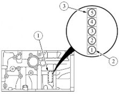
Figure 23 - Marking of the main journal diameter class on the cylinder block: 1 - location of marking of the class of diameters of main journals on the cylinder block; 2 - class of diameter of main journal No. 1 on the timing drive side; 3 - class of main journal diameter No. 5 from the flywheel installation side
The maximum diameter D of the cylinders, which requires replacement of the cylinder block, is 78.10 mm.
The cylinder diameter is measured in three zones in the longitudinal and transverse directions, as shown in Figure 24. The maximum size is determined by the most worn cylinder (bore gauge NI 50-100-1).
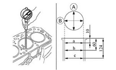
Figure 24 - Cylinder diameter measurement diagram: A. B - directions of measurements; a, b, c - measurement belts
The maximum permissible flatness of the cylinder block surface mating with the cylinder head is 0.1 mm per 100 mm of length (verification ruler, set of feeler gauges).
Take measurements as shown in Figure 25.
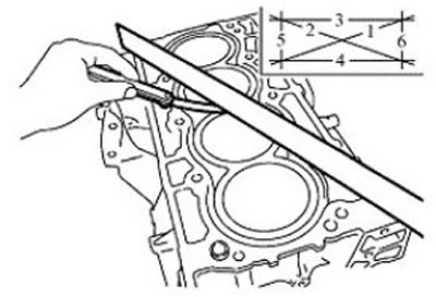
Figure 25 - Measuring the flatness of the cylinder block
Cylinder Block Reinforcement
The maximum non-flatness of the mating surfaces of the cylinder block reinforcement on the cylinder block side and on the oil pan side is 0.1 mm per 100 mm of length.
Take measurements as shown in Figure 26.
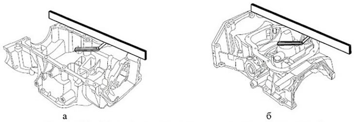
Figure 26 - Checking the flatness of the mating surfaces of the cylinder block amplifier
Crankshaft
The marking of the size groups of the connecting rod and main journals of the crankshaft is applied to the flange for installing the flywheel, Figure 27.
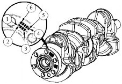
Figure 27 - Marking of classes of diameters of connecting rod and main journals of the crankshaft: 1 - size groups by diameter of bearings of crankshaft connecting rod journals; 2 - class of crankpin diameter on the timing drive side; 3 - class of crankpin diameter from flywheel side; 4 - size groups by diameter of crankshaft main journals; 5 - class of main journal diameter on the flywheel side; 6 - class of main journal diameter on the timing drive side
The classes of diameters of the crankshaft connecting rod journals are given in Table 3 (micrometer type MK 75-1).
Table 3 - Crankshaft journal diameter classes
Letter indicating the class of the diameter of the connecting rod journals on the crankshaft | Diameters of crankshaft connecting rod journals, mm |
A | 39,970 - 39,971 |
B | 39,969 - 39,970 |
C | 39,968 - 39,969 |
D | 39,967 - 39,968 |
E | 39,966 - 39,967 |
F | 39,965 - 39,966 |
G | 39,964 - 39,965 |
H | 39,963 - 39,964 |
J | 39,962 - 39,963 |
K | 39,961 - 39,962 |
L | 39,960 - 39,961 |
M | 39,959 - 39,960 |
N | 39,958 - 39,959 |
P | 39,957 - 39,958 |
R | 39,956 - 39,957 |
S | 39,955 - 39,956 |
T | 39,954 - 39,955 |
U | 39,953 - 39,954 |
The classes of diameters of the main journals of the crankshaft are given in Table 4 (micrometer type MK 75-1).
Table 4 - Crankshaft Main Journal Diameter Classes
Letter indicating the class of diameter of the main journals on the crankshaft | Diameters of crankshaft connecting rod journals, mm |
A | 47,978 - 47,979 |
B | 47,977 - 47,978 |
C | 47,976 - 47,977 |
D | 47,975 - 47,976 |
E | 47,974 - 47,975 |
F | 47,973 - 47,974 |
G | 47,972 - 47,973 |
H | 47,971 - 47,972 |
J | 47,970 - 47,971 |
K | 47,969 - 47,970 |
L | 47,968 - 47,969 |
M | 47,967 - 47,968 |
N | 47,966 - 47,967 |
P | 47,965 - 47,966 |
R | 47,964 - 47,965 |
S | 47,963 - 47,964 |
T | 47,962 - 47,963 |
U | 47,961 - 47,962 |
V | 47,960 - 47,961 |
W | 47,959 - 47,960 |
Check the radial runout of the crankshaft main journals (prisms, ICH-10 type indicator, SHM-PV-8 tripod). Radial runout should not be more than 0.01 mm.
Piston
Chips and cracks of any kind, burnouts, and destruction of partitions are not allowed (visual inspection).
The outer diameter D, figure 28, of the piston, measured at a distance L=10 mm, should be 77.948-77.958 mm (micrometer type MK 100-1).
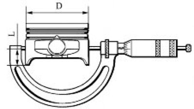
Figure 28 - Checking the piston diameter
The diameter of the hole for the piston pin should be 19.008 - 19.014 mm (bore gauge type NI 18-50-1).
Connecting rod
Diameter D, Fig. 29, of the hole for the piston pin in the upper head of the connecting rod should be 18.958-18.978 mm (bore gauge type NI 18-50-1).
According to the diameter of the hole D1 in the lower head, connecting rods are divided into several classes. The connecting rod class and cylinder number are marked on the cover and on the connecting rod body.
The classes of diameters of holes in the lower head of the connecting rod are given in Table 5 (bore gauge type NI 18-50-1).
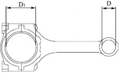
Figure 29 - Checking the diameters of the holes in the upper and lower heads of the connecting rod
Table 5 - Classes of diameters of holes in the lower head of the connecting rod
Letter indicating the class of the bore in the lower head of the connecting rod | Diameters of holes in the lower head of the connecting rod, mm |
A | 43,000 - 43,001 |
B | 43,001 - 43,002 |
C | 43,002 - 43,003 |
D | 43,003 - 43,004 |
E | 43,004 - 43,005 |
F | 43,005 - 43,006 |
G | 43,006 - 43,007 |
H | 43,007 - 43,008 |
J | 43,008 - 43,009 |
K | 43,009 - 43,010 |
L | 43,010 - 43,011 |
M | 43,011 - 43,012 |
N | 43,012 - 43,013 |
Check the thickness of the lower connecting rod head. The thickness of the lower connecting rod head should be within 18.748-18.800 mm (micrometer type MK 25-1).
Piston pin
No traces of wear or scoring on the piston pins after pressing out are allowed (visual inspection).
Check the outside diameter of the piston pin. The outer diameter of the piston pin should be within 18.996 - 18.998 mm (micrometer type MK 25-1).
Check the length of the piston pin. The length of the piston pin should be within 1 mm (caliper type ShTs-1-125-0,1).
Cylinder head
Check the cylinder head height. Height H, Fig. 30, of the cylinder head should be 125 mm (caliper gauge type ShR 250 or caliper depth gauge type ShG 250).
Check the flatness of the cylinder head surface mating with the cylinder block. Maximum permissible non-flatness of the mating surface of the cylinder head is 0.1 mm (verification ruler, set of feeler gauges).
Check the diameter of the camshaft bearings.
Install the centering bushings and camshaft bearing caps on the cylinder head, screw in and tighten the mounting bolts. Tightening torque of mounting bolts - 9.0...11.0 N·m (0.9...1.1 kgf·m) (replaceable head 8, torque wrench).
Measure the hole diameters for each cover. The diameter of the holes for the first cover 1, figure 31, should be 28.000-28.021 mm, for the holes of the 2 remaining covers 25.000-25.021 mm (bore gauge type NI 18-50-1).
Loosen the mounting bolts, remove the camshaft bearing caps and centering bushings from the cylinder head (replaceable head 8, ratchet).
Check the diameter of the valve guide holes. The maximum permissible diameter should not be more than 5.03 mm.
Check the diameter of the tappet sockets in the cylinder head. The diameter of the sockets should be 30.000 - 30.021 mm (bore gauge type NI 18-50-1).
Check the outside diameter of the valve lifters. The diameter should be between 29.977 - 29.987 mm (bore gauge type NI 18-50-1).
There should be no signs of wear or cracks in the coating on the surface of the pushers (visual inspection).
Valve
Unilateral wear of the valve stem along the working surface is not permitted (visual inspection).
Determine the wear and condition of the valve plates. Not allowed: cracks, chips, one-sided wear (visual inspection).
Determine the wear of the valve stem end face, grind the end face if necessary (visual inspection).
Permissible valve dimensions, figure 32, after grinding according to table 6 (micrometer type MK 50-1, indicator type ICH-10, tripod type SHM-PV-8, calibration prism, caliper type SCHTS-1-125-0,1).
Valve spring
Free spring length 42.26 mm (caliper type ShchTs-1-125-0.1).
Spring length under load 145±9 N (14.5±0.9 kgf) 34.4 mm (caliper type ShchTs-1-125-0.1).
Deviation t, figure 33, of the spring from perpendicularity should not be more than 1.6 mm (test plate, test square, feeler gauge set).