



Place the connecting rods in an electric oven heated to 240°C. The top heads of the connecting rods must be directed towards the inside of the furnace. The heating time of the connecting rods in the furnace is not less than 15 minutes (electric furnace type SNOL-3.5, gloves).
Install the piston pin 2 and guide 3 on the roller of the device 1, Fig. 41 (fixture 67.7823-9703L).
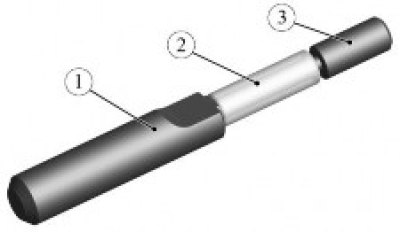
Figure 41 - Installing the piston pin on the fixture: 1 - device 67.7823-9703L; 2 - piston pin; 3 - device guide
Remove the heated connecting rod from the electric furnace, quickly secure it by the lower head in a vice so that the installation mark 1, Figure 42, is located on the side where the piston pin is installed (vice with aluminum pads, gloves).
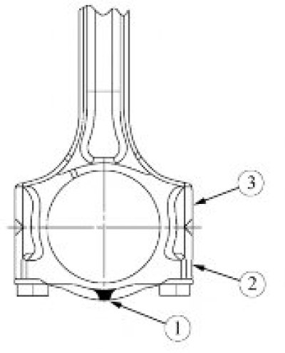
Figure 42 - Location of the installation mark: 1 - installation mark (connecting rod cap lug); 2 - connecting rod cover; 3 - connecting rod
Place the piston on the connecting rod head so that the installation mark (point on the piston bottom) located on the side where the piston pin is installed, align the hole for the piston pin with the hole in the upper head of the connecting rod and insert the device assembled with the piston pin into the hole until the shoulders of the mandrel stop against the piston boss. In this case, the piston should be pressed with its boss against the upper head of the connecting rod against the direction of pressing of the pin.
Repeat the operations for the remaining pistons.
Loosen the mounting bolts and remove the connecting rod caps (replacement head 11, ratchet and extension).
Select connecting rod bearings according to the classification of connecting rod journals of the crankshaft and holes in the lower heads of the connecting rods in accordance with Table 8.
The color in the table indicates the marking of the insert applied to its end. The color of the marking corresponds to a specific class of the bearing shell, which must be installed depending on the class of the diameter of the connecting rod journals and the class of the diameter of the holes in the lower heads of the connecting rods.
The upper part of the table shows the classes of diameters of the holes in the lower heads of the connecting rods, and the left part shows the classes of diameters of the connecting rod journals of the crankshaft.
Abbreviations given in Table 6:
- UPR - connecting rod insert;
- LWR - a bearing insert installed in the connecting rod cap.
Install piston rings on the pistons. Install the lower compression ring with the scraper facing down. The orientation of the piston ring locks is shown in Figure 43 (pliers for removing and installing piston rings).
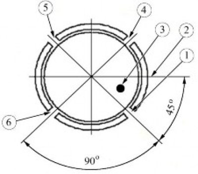
Figure 43 - Orientation of piston ring locks: 1, 5 - location of oil scraper ring locks; 2 - piston pin axis; 3 - installation mark (dot) on the piston; 4 - location of the lower compression ring lock and the joint of the oil scraper ring expander; 6 - location of the upper compression ring lock
Install the bearing shell with the hole in the connecting rod flush with the parting plane, as shown in Figure 44. Move the bearing shell from the opposite side until it is aligned with the parting plane.
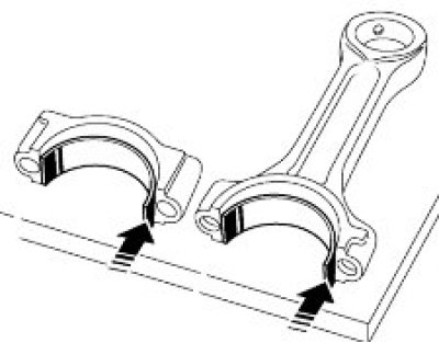
Figure 44 - Installing the liners in the connecting rods and in the connecting rod caps
Adjust the position of the bearing shell so that the hole in the bearing shell completely matches the hole in the connecting rod and the distance from the side surfaces of the connecting rod to the bearing shell on each side is the same (depth gauge type ShG 250).
Repeat the operations for installing the bearing shells for the remaining connecting rods.
Install the bearing shell without a hole into the connecting rod cap, flush with the parting plane, as shown in Figure 44. Move the bearing shell from the opposite side until it is aligned with the parting plane.
Adjust the position of the insert so that the distance from the side surfaces of the lid to the insert on each side is the same (depth gauge type ShG 250).
Repeat the insert installation operations for the remaining covers.
Lubricate the cylinders, liners, piston skirts, and crankshaft connecting rod journals with engine oil (engine oil in accordance with Appendix A of the current "Consumption standards for primary and auxiliary materials for maintenance and repair of LADA vehicles").
Install device 2 on piston 1, figure 45, so that the piston skirt protrudes from the device by approximately 1 cm (piston installation tool).
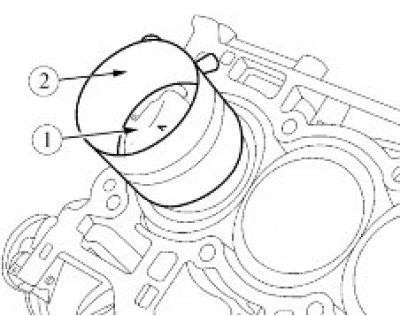
Figure 45 - Installing the piston: 1 - piston; 2 - device for installing the piston
(Full article on the website: LadaMan)
Compress the piston rings and install the piston assembly with the connecting rod into the cylinder, in accordance with the marking. The mark on the piston bottom should face the timing drive.
Repeat the operations for the remaining three pistons.
Install the connecting rod caps according to the markings. The markings on the cover and on the connecting rod must correspond to the cylinder number.
Install and tighten new connecting rod cap bolts.
Tighten the main bearing cap bolts in two steps (replaceable head 11, ratchet, extension, torque wrench, angle measuring head):
- tighten the bolts to a tightening torque of 19...20 N·m (1.9...2.0 kgf·m);
- tighten the bolts to an angle of 60°...65°.
Install a new cylinder block reinforcement seal ring and two centering pins into the cylinder block. The protrusion of the pins from the cylinder block is 9...11 mm (hammer, SHG 250 type shtangenglubinometer).
Apply a bead of sealant with a diameter of 4-5 mm, Figure 46, to the plane of the cylinder block amplifier joint with the cylinder block at a distance of 6.5 mm from the inner edge of the amplifier (silicone sealant TV 1217 L, consumption rate - 14 g).
Attention! The open time of the sealant is no more than 5 minutes.
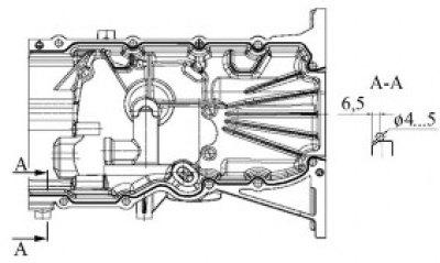
Figure 46 - Scheme of applying sealant to the plane of the cylinder block amplifier connector
Install the cylinder block booster on the cylinder block and secure with ten bolts in the order shown in Figure 47. Bolt tightening torque-21.0...29.0 N·m (2.1...2.9 kgf·m) replacement head 10, crank, extension cable, torque wrench).
Remove any remaining sealant (white spirit, wiping rags).
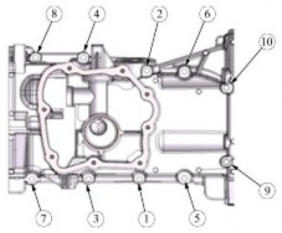
Figure 47 - Cylinder block reinforcement mounting bolt tightening sequence
Apply a bead of sealant with a diameter of 4...5 mm, Figure 48, to the plane of the joint between the oil pan cover and the cylinder block amplifier at a distance of 6.5 mm from the inner edge of the amplifier (silicone sealant TV 1217 L, consumption rate - 8 g).
Attention! The open time of the sealant is no more than 5 minutes.
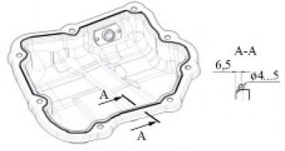
Figure 48 - Scheme of applying sealant to the joint plane of the oil pan cover
Install the oil pan cover on the cylinder block amplifier and secure with eight bolts in the order shown in Figure 49. Tightening torque of the bolts is 8.12 N·m (0.8...1.2 kgf·m) (replaceable head 8, ratchet, extension, torque wrench).
Remove any remaining sealant (white spirit, wiping rags).
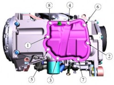
Figure 49 - Tightening order of oil pan cover mounting bolts