



Note: catalog number of parts of this unit see here.
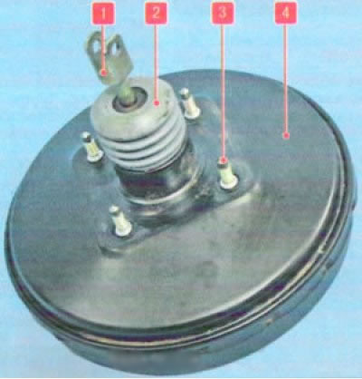
Vacuum brake booster: 1 - pusher; 2 - protective cover with filter; 3 - amplifier mounting pin; 4 - amplifier body
The brake booster is installed under the hood on the front shield of the body, it is located between the brake pedal and the master brake cylinder.
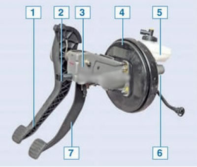
Pedal assembly with vacuum booster and master brake cylinder: 1 - Clutch pedal: 2 - Brake light switch: 3 - Pedal assembly bracket; 4 - brake booster: 5 - hydraulic system reservoir; 6 - master brake cylinder; 7 - brake pedal
Removal
Place the vehicle in the work area, apply the parking brake and turn off the ignition.
Loosen the nuts securing the master brake cylinder (see here).
Note: You do not need to disconnect the brake pipes from the brake cylinder - this will prevent air from entering the system.
Carefully remove the brake cylinder assembly with the reservoir from the booster studs and set it aside.
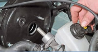
Remove the check valve from the vacuum booster housing (see here).
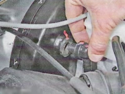
After which, in the car...
... disconnect the vacuum booster from the brake pedal by turning the spring retainer of the finger 3, Figure 4-1,
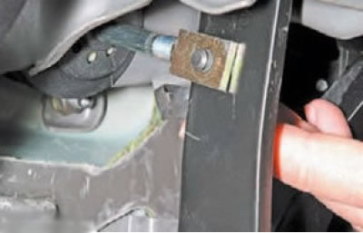
use a screwdriver to pry off the plastic retaining ring
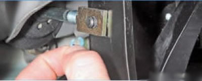
up and remove the pin (axis) from the holes of the vacuum booster pusher and brake pedal.
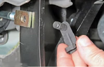
Note: If the pin (axle) with the spring retainer is worn, replace it.
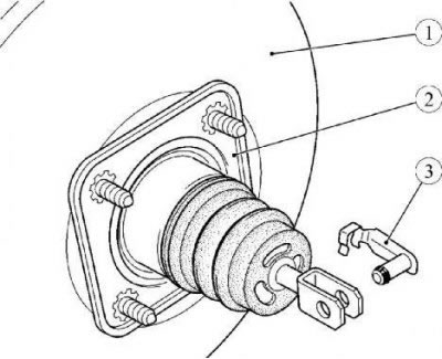
Figure 4-1 - Removing the brake booster: 1 - brake booster; 2 - gasket; 3 - finger (connecting axis)
Remove the two spring washers securing the noise insulation pad from the pedal assembly mounting studs (flat head screwdriver).
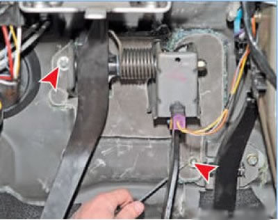
and remove the overlay
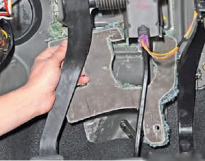
Unscrew the four nuts 2, Figure 4-2, securing the vacuum booster to the bracket 1 of the pedal assembly (replaceable head 13, extension, ratchet wrench).
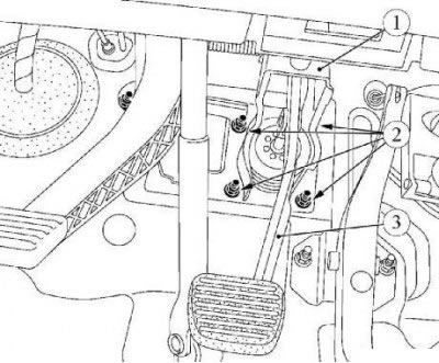
Figure 4-2 - Removing the brake booster: 1 - pedal assembly bracket; 2 - vacuum booster mounting nuts; 3 - brake pedal
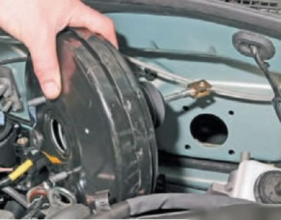
... and remove the brake booster
Installation
Attention. Before installation, check the presence and condition of gasket 2, Figure 41, between the vacuum booster and the front shield, replace if necessary.
Attention. The connecting axis (pin) 3 between the vacuum booster pusher and the brake pedal must be replaced.
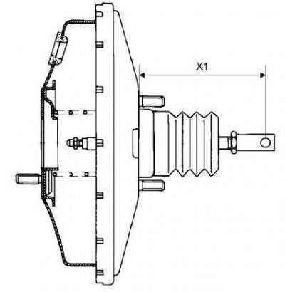
Figure 4-3 - Adjusting the brake booster rod extension: X1 - the value of the rod extension
Attention: Before installation, Figure 4-3, check the size X1 = 145.8 ±0.5 mm, adjust if necessary.
Note: The booster rod adjusting bolt is secured against self-loosening with thread lock.
Install the brake booster in place and secure it to the front shield and pedal bracket with four nuts. Tightening torque of nuts 21 Nm (2.1 kgf·m) (replaceable head 13, extension, ratchet wrench, torque wrench).
Connect the vacuum booster to the brake pedal by installing a new connecting axle (pin) into the holes in the booster pushrod and the brake pedal and snapping the axle flag onto the pushrod rod. The axis is installed only by moving from right to left and from top to bottom. Before installation on the axle, apply 1 g of MOLYCOTE ZZM grease (MOLYCOTE ZZM plastic grease according to the current "Codifier of main and auxiliary materials used in maintenance and repair of LADA vehicles" K 3100.25100.00018).
Install the soundproofing pad in place and secure it with two spring washers (technological tube).
Install the brake booster check valve in place.
Install the brake master cylinder.
Bleed the brake system and clutch hydraulic drive. (see here).
Adjust the brake light switch. (see here).
Check the efficiency of the service brake system.