
Note. See part numbers for this assembly. Here and Here.
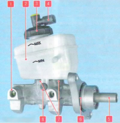
Master brake cylinder assembly with reservoir: 1 - main brake cylinder; 2 - GTZ tank; 3 - tank cover; 4 - brake fluid level sensor; 5 - piston pusher; 6 - sealing ring; 7 - connecting sleeves (not visible in the photo, as they are closed by a tank); 8 - tank fastening pin
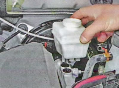
The master brake cylinder is located under the hood and is mounted on the vacuum brake booster. The brake fluid reservoir is mounted directly on the cylinder (see photo 2-2).
Removing
Note. GTZ can be removed as an assembly with a tank, and sequentially (those. you can replace the tank without removing the cylinder). This section describes serial removal. If you need to remove the cylinder assembly, then the procedure for removing the GTZ reservoir can be skipped.
Put the car on the working place, brake with the parking brake and turn off the ignition.
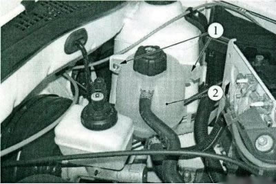
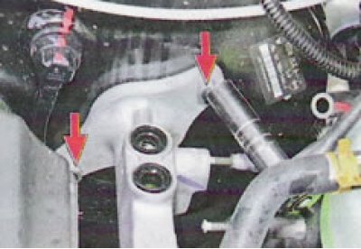
Figure 2-1 - Mounting the expansion tank: 1 - expansion tank nuts; 2 - expansion tank
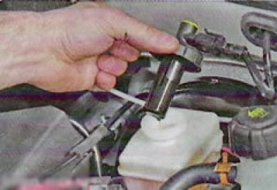
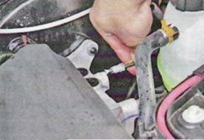
Unscrew the two nuts 1, Figure 2-1, fastening the expansion tank 2 and move the tank to the side without draining the liquid from it (interchangeable head 10, extension and collar).
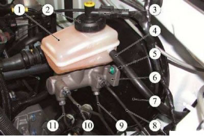
Figure 2-2 - Brake master cylinder for non-ABS vehicles: 1 - reservoir of the brake master cylinder; 2 - plug assembly with brake fluid level sensor; 3 - block of the wiring harness to the brake fluid level sensor; 4 - hose to the clutch master cylinder; 5 - nut for fastening the brake master cylinder; 6 - brake master cylinder; 7 - vacuum brake booster; 8 - brake pipe to the left front brake mechanism; 9 - brake pipe to the right rear brake mechanism; 10 - brake pipe to the right front brake mechanism; 11 - brake pipe to the left rear brake mechanism
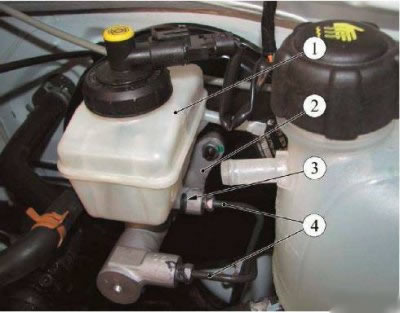
Figure 2-3 - Brake master cylinder for vehicles equipped with ABS: 1 - reservoir of the brake master cylinder; 2 - brake master cylinder; 3 - retainer for fastening the reservoir to the brake master cylinder; 4 - brake pipes to the ABS hydraulic unit
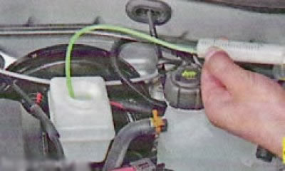
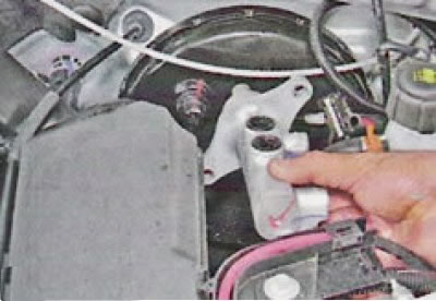
Disconnect connector 3, Figure 2-2, of the harness from the brake fluid level sensor.

Unscrew and remove plug 2 complete with brake fluid level sensor.
Drain brake fluid from reservoir 1, Figure 2-2 or 2-3.
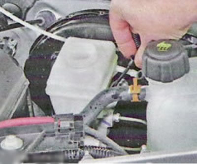
Remove the hose from the tank fitting. (do not lower the hose down, there is brake fluid in it. Fix it in any way in the upper position)
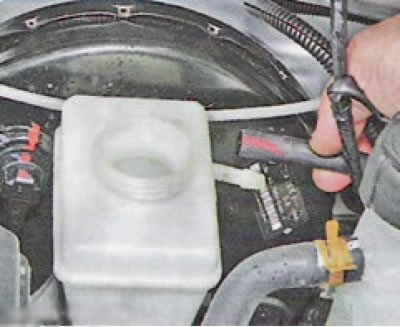
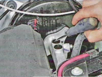
Pry off with a thin tool and remove retainer 3, Figure 2-3, securing the reservoir to the brake master cylinder.
Remove the reservoir, removing its branch pipes from the connecting bushings of the brake cylinder.
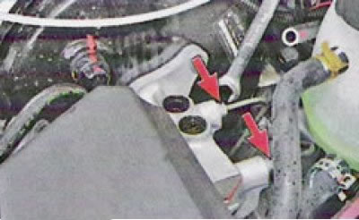
If during the operation of the car there was a leakage of brake fluid from the connection of the reservoir with the GTZ, then remove the connecting sleeves from the holes and...
... replace them with new ones.
Install plugs into the openings in the master cylinder.
Loosen the nuts securing the two pipes to the brake master cylinder (wrench for brake pipes type 41 08 11 13 f. "Stahlwille")
Disconnect brake pipe fittings 4 from brake master cylinder 2, place pipes aside.
Install technological plugs in the holes of the master cylinder and on the brake pipes.
Remove two nuts 5, Figure 2-2, securing the brake master cylinder to the vacuum booster (interchangeable head 13, extension, ratchet wrench).
And remove the brake master cylinder.
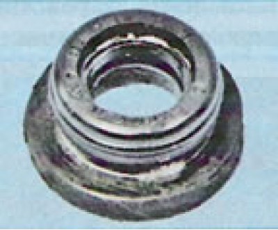
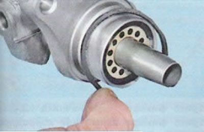
Remove the rubber o-ring from the GTZ body.
Installation
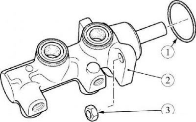
Figure 2-4 - Installing the brake master cylinder: 1 - sealing ring; 2 - brake master cylinder; 3 - nut for fastening the brake master cylinder to the vacuum booster
Attention. Be sure to replace the O-ring 1, Figure 2-4, of brake master cylinder 2 before installation.
Attention. In case of leakage of working fluid from the brake master cylinder into the vacuum booster, be sure to replace the brake master cylinder - vacuum booster assembly.
A vacuum brake booster with a rubber diaphragm that has been exposed to brake fluid becomes unusable.
Install the brake master cylinder in place and align it with the vacuum booster so that the booster push rod fits into the socket in the master cylinder housing.
Attach the brake master cylinder to the vacuum booster housing with two nuts. Nut tightening torque 21 Nm (2.1 kgf·m) (interchangeable head 13, extension, ratchet wrench, torque wrench).
Remove the plugs from the brake pipes and the holes of the brake master cylinder, attach the brake pipes to the master cylinder and tighten the fittings. Tightening torque of fittings 14 Nm (1.4 kgf·m) (wrench for brake pipes type 41 08 11 13 f. "Stahlwille", interchangeable insert 11 type 58 23 10 11 f. "Stahlwille", torque wrench type 50 18 00 04 f. "Stahlwille").
Remove the plugs from the holes of the brake master cylinder, install the hydraulic reservoir on the cylinder and secure it with a retainer.
Reinstall expansion tank 2, Figure 2-1, and secure with two nuts 1. Tightening torque of nuts 8 Nm (0.8 kgf·m) (interchangeable head 10, extension and knob, torque wrench).
Bleed the brake system and hydraulic clutch. (see here).
Install the brake cylinder reservoir cap and connect the wiring harness connector to the brake fluid level indicator sensor.
Check the efficiency of the service brake system.