



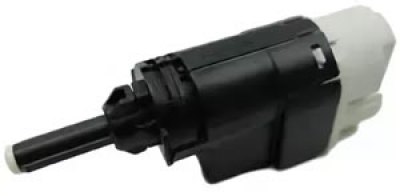
Removal
Place the vehicle on the work post, apply the parking brake and turn off the ignition.
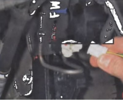
Disconnect the wiring harness connector from the brake light switch.
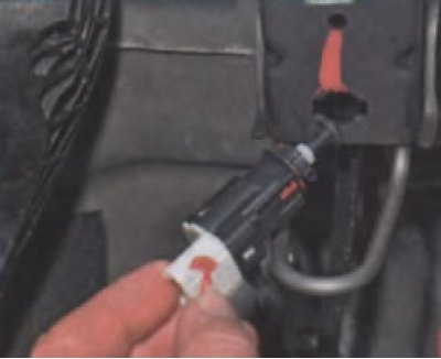
Remove the brake light switch by turning it a quarter turn counterclockwise.
Installation
Caution: Incorrect adjustment of the brake light switch may cause premature wear of the brake pads and may cause abnormal operation of the electronic engine control system (ECM).
Caution: To ensure normal operation of the brake light switch:
- it is not allowed to remove the movable toothed rod from it; when disconnecting the rod from the switch, the switch must be replaced;
- it is not allowed to adjust the extension of the switch rod more than three times; after three unsuccessful attempts at adjustment, the switch must be replaced;
- after removing the switch or violating the adjustment during routine maintenance, the switch must be replaced.
Before installing the brake light switch, it is necessary to adjust the toothed rod extension.
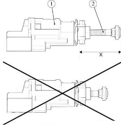
Figure 7-1 - Adjusting the Brake Light Switch Rod Extension: 1 - brake light switch; 2 - brake light switch rod; X - adjustment size
Measure the extension of the rod 2, Figure 7-1, the extension value should correspond to the dimension X = 28 mm. If it does not correspond, carefully pull the rod out of the switch 1 by the specified value (metal ruler).
Make sure the brake pedal is securely connected to the brake booster pushrod. Press brake pedal 1, Figure 7-2, by hand. Keeping the brake pedal pressed, install the brake light switch into the hole in bracket 3 of the pedal assembly and secure it by turning it a quarter turn clockwise. Carefully return the brake pedal to its original position.
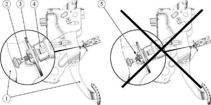
Figure 7-2 - Installing the brake light switch: 1 - brake pedal; 2 - brake light switch rod; 3 - pedal assembly bracket; 4 - brake light switch; 5 - rod bushing
When the brake pedal is returned, the extension of the rod 2 of the brake light switch is automatically adjusted (the rod is pressed into the switch to the required value, characteristic clicks of the rod teeth passing through fixed positions are heard).
After returning the pedal, check the protrusion of the bushing 5 of the switch rod; the bushing must not protrude beyond the end of the switch housing 4; if the bushing protrudes, the adjustment must be repeated.
Final adjustment of the brake light switch
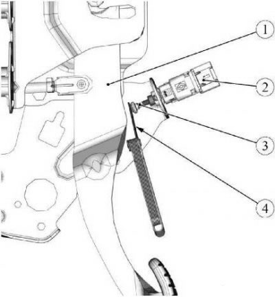
Figure 7-3 - Final adjustment of the brake light switch: 1 - brake pedal; 2 - brake light switch; 3 - brake light switch rod; 4 - 2mm thick feeler gauge
Press the brake pedal with your hand.
Install a 2 mm thick feeler gauge 4 between the rod 3, Figure 7-3, of the switch and the brake pedal 1 and carefully return the pedal to its original position (2 mm feeler gauge).
Depress the pedal again and remove the dipstick.
Adjustment completed.
Connect the wiring harness connector to the brake light switch.