



Open large image in new tab »
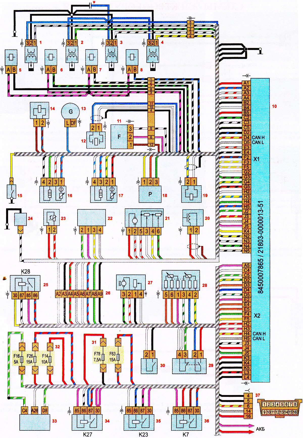
Engine control system diagram: 1 - ignition coil of the first cylinder; 2 - ignition coil of the second cylinder; 3 - ignition coil of the third cylinder; 4 - ignition coil of the fourth cylinder; 5 - injector of the first cylinder; 6 - injector of the second cylinder; 7 - injector of the third cylinder; 8 - fourth cylinder injector; 9 - capacitor; 10 - Electronic control unit (ECU); 11 - camshaft position sensor; 12 - knock sensor; 13 - generator; 14 - electromagnetic valve of the air intake system; 15 - oil pressure sensor; 16 - oxygen concentration sensor (diagnostic); 17 - oxygen concentration sensor (control); 18 - air conditioning compressor pressure sensor; 19 - purge valve of the adsorber; 20 - crankshaft position sensor; 21 - throttle assembly; 22 - mass air flow sensor; 23 - coolant temperature sensor; 24 - air conditioning compressor clutch; 25 - air conditioning compressor clutch relay K.28; 26 - junction block; 27 - fuel module; 28 - electronic gas pedal; 29 - brake pedal position sensor; 30 - Clutch pedal position sensor; 31 - fuse and relay box in the engine compartment; 32 - fuse and relay box in the passenger compartment; 33 - electrical equipment control unit; 34 - main relay of the engine management system K27; 35 - starter relay K23; 36 - fuel pump relay K7; 37 - diagnostic connector block