
Car repair AvtoVAZ Car repair Renault Car repair Hyundai Car repair Ford Car repair Volkswagen Car repair Audi Car repair Chevrolet
English Русский
Български
Беларускі
Український
Српски
Hrvatski
Română
Polski
Slovenský
Magyar
articles sitemap contacts bookmark
LadaMan.ru


Kalina Granta Priora Vesta Largus XRAY
Priora 1 (2007-2018, VAZ-2170)

Replacement of fuel vapor recovery system components (Priora 2170)

  • Main
  • Priora
  • Priora 1
  • Power unit
  • Supply system
  • Replacement of fuel vapor recovery system components
0
Fuel vapor recovery system components (adsorber, fuel vapor separator, adsorber purge valve, gravity valve) remove for inspection or replacement if a persistent smell of gasoline appears, caused by leaks in components and pipelines, as well as failure of the adsorber purge valve. In addition, a leaky adsorber and a failure of the purge valve can cause the engine to run unsteadily at idle speed, even to the point of stopping.

You will need: a 10 mm wrench and a flat-blade screwdriver.

Note: Before removing the fuel vapor recovery system components, disconnect the wire from the negative terminal of the battery.
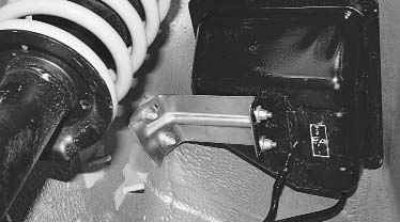

Fuel vapor separator installed in the niche of the left rear wheel.


Fuel vapor separator installed in the niche of the left rear wheel.

1. Place the vehicle on a lift or inspection pit.

2. Remove the left rear wheel (see "Wheel change").
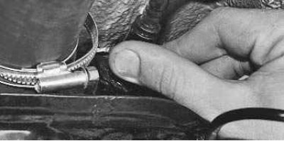
3. To remove the separator, squeeze the quick release connector lock…

3. To remove the separator, squeeze the quick release connector lock…


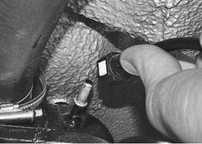
4. …and remove the fuel drain tube from the fuel tank nipple.

4. …and remove the fuel drain tube from the fuel tank nipple.

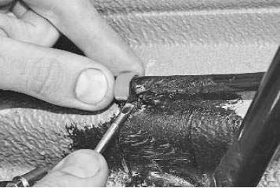
5. Use a screwdriver to pry up the fuel drain tube holder…
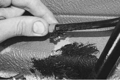

5. Use a screwdriver to pry up the fuel drain tube holder…

6. …and release the holder together with the tube.

6. …and release the holder together with the tube.

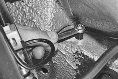
7. Unscrew the nut securing the holder of the steam outlet tube from the separator to the adsorber.

7. Unscrew the nut securing the holder of the steam outlet tube from the separator to the adsorber.


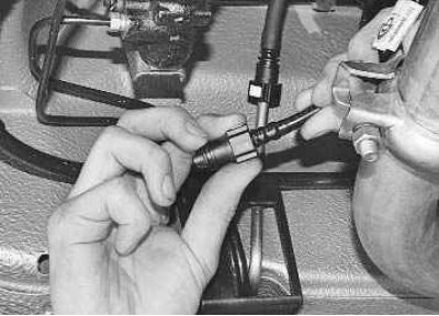
8. Disconnect the steam pipes by squeezing the quick-release connector lock.

8. Disconnect the steam pipes by squeezing the quick-release connector lock.

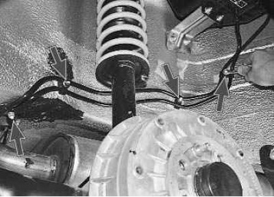
9. Unscrew the four nuts securing the holders of the steam outlet pipe and the fuel drain pipe.
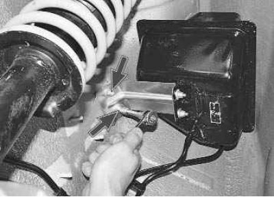

9. Unscrew the four nuts securing the holders of the steam outlet pipe and the fuel drain pipe.

10. Unscrew the two nuts securing the separator bracket to the body…
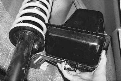

10. Unscrew the two nuts securing the separator bracket to the body…

11. …and remove the separator assembly with the bracket, tubes and gravity valve.
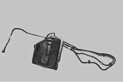

11. …and remove the separator assembly with the bracket, tubes and gravity valve.


Note: This is what the assembled separator looks like. Purchase an identical replacement complete…


Note: This is what the assembled separator looks like. Purchase an identical replacement complete with tubes and gravity valve, as the tubes are not removable.


12. Install the fuel vapor separator in the reverse order of removal.
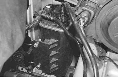
Adsorber the fuel vapor recovery system is installed in the engine compartment on the right side of…


Adsorber the fuel vapor recovery system is installed in the engine compartment on the right side of the radiator grille. Due to the specific layout of the vehicle, access to its mount directly on the vehicle is quite simple.
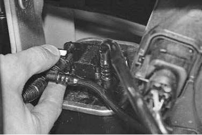
1. To remove the canister, squeeze the quick-release connector lock…
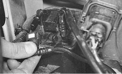

1. To remove the canister, squeeze the quick-release connector lock…


2. …and remove the fuel vapor supply pipe to the purge valve. Similarly, disconnect the fuel vapor…


2. …and remove the fuel vapor supply pipe to the purge valve. Similarly, disconnect the fuel vapor intake tube from the separator.
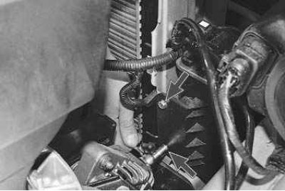
3. Unscrew the two bolts securing the adsorber…

3. Unscrew the two bolts securing the adsorber…

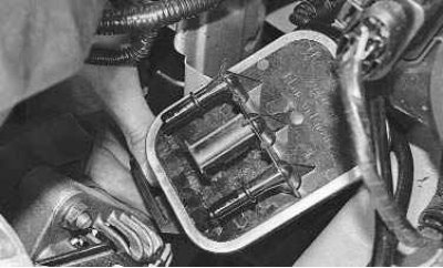
4. ...and remove the adsorber.
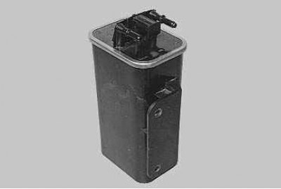

4. ...and remove the adsorber.

Note: This is what the adsorber looks like. Purchase exactly the same one as a replacement.


Note: This is what the adsorber looks like. Purchase exactly the same one as a replacement.


5. Install the canister in the reverse order of removal.
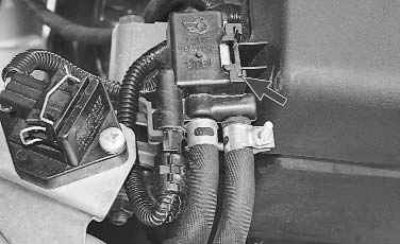
Evaporative Canister Purge Valve installed in the engine compartment on the decorative engine cover.
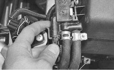

Evaporative Canister Purge Valve installed in the engine compartment on the decorative engine cover.

1. To remove the valve, press the retainer…
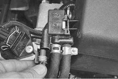

1. To remove the valve, press the retainer…

2. …and disconnect the wiring harness connector from the valve.
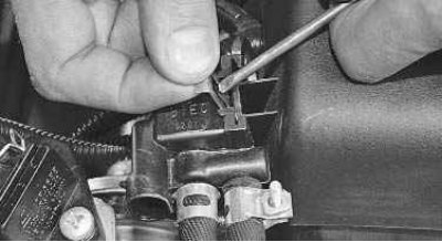

2. …and disconnect the wiring harness connector from the valve.

3. Press the spring clamp lock…
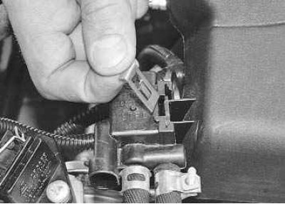

3. Press the spring clamp lock…

4. …remove the clamp…
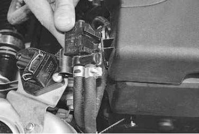

4. …remove the clamp…

5. …and remove the valve from its mounting bracket.
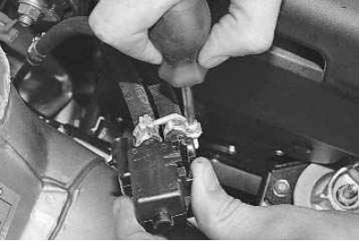

5. …and remove the valve from its mounting bracket.

6. Loosen the clamp securing the fuel vapor supply hose from the adsorber…
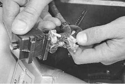

6. Loosen the clamp securing the fuel vapor supply hose from the adsorber…

7. …and disconnect the hose from the purge valve fitting.
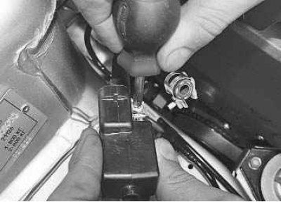

7. …and disconnect the hose from the purge valve fitting.

8. Loosen the clamp securing the fuel vapor supply hose to the throttle assembly…
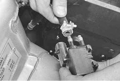

8. Loosen the clamp securing the fuel vapor supply hose to the throttle assembly…

9. …and disconnect the hose from the valve fitting.
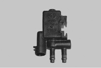

9. …and disconnect the hose from the valve fitting.

Note: This is what the purge valve looks like. Purchase exactly the same one as a replacement.


Note: This is what the purge valve looks like. Purchase exactly the same one as a replacement.


10. Install the purge valve in the reverse order of removal.


This article is available at russian, bulgarian, belarusian, ukrainian, serbian, croatian, romanian, polish, slovak, hungarian
This article has been reviewed: Vladislav Voloshin
Share with friends:
◀ Previous
Lada Priora 1: Supply system
 

Replacing the throttle cable
Checking and replacing injectors
Removal and installation the fuel rail
Replacing the idle speed control valve
Removal and installation the throttle assembly
 
More articles with information from manuals for Lada:

• Replacement of fuel vapor recovery system components Lada Kalina Sedan (2004-2013, VAZ-1118)
• Features of operation of a car with a fuel injection system Lada Granta 1 (2011-2023, VAZ-2190)
• Increased fuel consumption Lada Vesta 1 (2015-2023, VAZ-2180)
• Fuel vapor adsorber Lada Largus 1 (2012-2023)
• Fuel vapor recovery system steam lines Lada X-Ray 1 (2015-2022)
Link to this article in various formats
Reviews and comments of visitors
No comments yet


Add up two numbers: 19 + 48


Priora 1 (2007-2018) 
  • General information
  • Vehicle device
  • User manual
  • Faults en route
  • Maintenance
  • Power unit
  • Engine repair
  • Cooling and lubrication system
  • Supply system
  • Exhaust system
  • Transmission
  • Clutch
  • Car gearbox
  • Drive shafts
  • Chassis (running gear)
  • Car suspension
  • Steering
  • Brake system
  • Body and interior
  • Exterior (external elements)
  • Interior (internal elements)
  • Doors, locks and windows
  • Electrical equipment
  • Equipment and devices
  • Power devices
  • Lighting and signaling
  • Cooling and heating
  • Electrical circuits
LadaMan.ru © 2018–2026 | Mobile version | About Lada | Sitemap: EN BG BY UA RS HR RO PL SK HU | Contacts with admin | | Add to bookmarks
Kalina Hatchback (2004-2013) | Kalina Sedan (2004-2013) | Granta 1 (2011-2023) | Priora 1 (2007-2018) | Vesta 1 (2015-2023) | Largus 1 (2012-2023) | X-Ray 1 (2015-2022) |
This site uses cookies to ensure everything runs smoothly.