



Removal
Steam pipe from fuel tank to adsorber
Place the vehicle on a two-post lift and apply the parking brake (electro-hydraulic lift type P-3.2G with a lifting capacity of 3.2 t).
Remove the right front wheel in accordance with the requirements of TI 3100.25100.20594.
Raise the vehicle to a height convenient for performing the work.
Remove the right inner trim and the right side mudguard in accordance with the requirements of TI 3100.25100.20599.
Press the spring clamps of the tip of tube 1, Figure 8-12, of the steam line from the fuel tank to the adsorber and, by moving along the axis of the fitting, disconnect it from the adsorber 3.
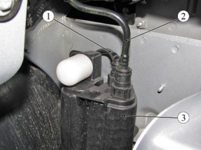
Figure 8-12 - Connecting the fuel vapor recovery tubes to the canister: 1 - steam pipe from the fuel tank to the adsorber; adsorber; 2 - steam pipe from the adsorber to the adsorber purge valve 3 - adsorber
Unscrew nuts 1, figure 8-5, and bolt 2, remove protective screen 3 of pipelines (replacement head 10, extension, ratchet).
Press the spring clamps of the tip of tube 1, Figure 8-7, of the steam line from the fuel tank to the adsorber and, by moving along the axis of the fitting, disconnect it from the steam line tube of the fuel tank.
Press the clamps and disconnect the brackets 1, Figure 8-11, securing the pipelines from the vehicle body (flat head screwdriver).
Disconnect the steam pipe 3 from the pipe mounting brackets and remove it from the vehicle.
Steam pipe from the adsorber to the adsorber purge valve
Place the vehicle on a two-post lift and apply the parking brake (electro-hydraulic lift type P-3.2G with a lifting capacity of 3.2 t).
Remove the right front wheel in accordance with the requirements of TI 3100.25100.20594.
Raise the vehicle to a height convenient for performing the work.
Remove the right inner trim and the right side mudguard in accordance with the requirements of TI 3100.25100.20599.
Press on the spring clamps of the tube tip 2, Figure 8-12, of the steam line from the adsorber to the adsorber purge valve and, by moving along the axis of the fitting, disconnect it from the adsorber 3.
Press the spring clamps of the tip of the steam pipe from the adsorber to the adsorber purge valve, move it along the axis of the fitting to disconnect it from the adsorber purge valve and remove the pipe from the vehicle.
Steam pipe from the purge valve of the adsorber to the intake module.
Place the vehicle in the work area, apply the parking brake and turn off the ignition.
Remove the intake module screen.
Press the spring clamps of the steam pipe tip and, by moving along the axis of the fitting, disconnect the pipe from the fitting of the inlet module.
The text of the article was taken from the website [LADAman]
Press the spring clamps of the steam pipe tip and, by moving it along the axis of the fitting, disconnect the pipe from the fitting of the adsorber purge valve.
Disconnect the steam line tube from the mounting brackets on the intake module and the body and remove the tube from the vehicle.
Installation
Install the steam pipes on the vehicle in the reverse order of removal.
Attention: The steam pipe tips have black clamps.
When installing steam pipes, connect the pipe ends to the fittings until the spring lock clicks. After installation, check the reliability of the tubes.