



Removal
Place the vehicle on a two-post lift and apply the parking brake (electro-hydraulic lift type P-3.2G with a lifting capacity of 3.2 t). Fold the rear seat cushion forward.
Remove cover 1, Figure 8-1, of the fuel pump hatch.
Disconnect block 1, Figure 8-2, from MEBN 2.
Start the engine and let it run at idle speed until it stops completely to relieve pressure in the fuel system, ensuring the removal of exhaust gases (exhaust reel with fan type SERF/SP). Turn off the ignition.
Disconnect the ground wire terminal from the battery (spanner 10).
Raise the vehicle and drain as much fuel as possible from the fuel tank. When pumping out fuel, take measures to prevent leakage (brush pump, fuel canister).
Remove the right rear wheel in accordance with the requirements of TI 3100.25100.20594.
Unscrew the two screws 1, Figure 8-3, self-tapping fastenings of the filler neck
2 fuel tanks to the body (screwdriver with Torx T20 bit).
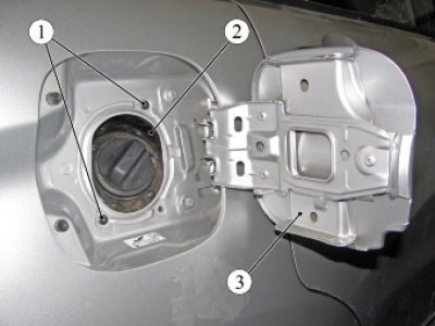
Figure 8-3 - Fastening the fuel tank filler neck: 1 - self-tapping screw; 2 - fuel tank filler neck; 3 - fuel tank filler hatch
Unscrew nut 1, Figure 8-4, and remove the terminal of wire 2 "ground" from the mounting stud on the body under the arch of the rear right wheel (replacement head 10, extension, ratchet).
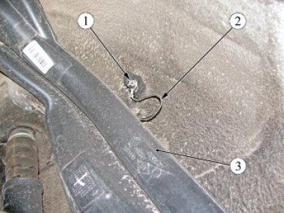
Figure 8-4 - Fastening the ground wire of the fuel tank filler pipe: 1 - nut; 2 - fuel tank filler pipe; 3 - "ground" wire
Unscrew nuts 1, figure 8-5, and bolt 2, remove protective screen 3 of pipelines (replacement head 10, extension, ratchet).
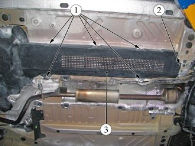
Figure 8-5 - Fastening the pipeline protective screen: 1 - nut; 2 - bolt; 3 - protective screen of pipelines
Remove the holders 1, Figure 8-6, of the heat shield (flat head screwdriver, cross head screwdriver, pliers).
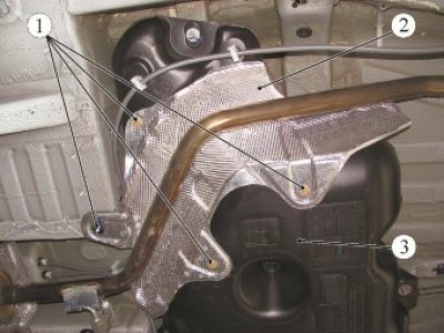
Figure 8-6 - Fastening the fuel tank heat shield: 1 - holder; 2 - fuel tank heat shield; 3 - fuel tank
Remove the heat shield 2 from the fuel tank.
Disconnect the exhaust system from the exhaust manifold and the vehicle body in accordance with the requirements of Section 9 of this TI.
Move the front part of the exhaust system to the left and secure it to the left arm of the front suspension (technological hook).
Press the spring clamps of the tube connectors 1 and 2, Figure 8-7, and by moving along the axis of the fittings, disconnect the tubes from the fuel tank 3.
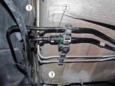
Figure 8-7 - Disconnecting the pipes from the fuel tank: 1 - steam pipe from the fuel tank to the adsorber; 2 - fuel pipe; 3 - fuel tank
Disconnect the parking brake cables 1, Figure 8-8, from the holders on the body and fuel tank.
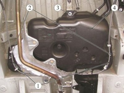
Figure 8-8 - Removing the fuel tank: 1 - parking brake cable; 2 - fuel tank mounting nut; 3 - fuel tank mounting bolt; 4 - fuel tank
Unscrew two nuts 2 and two bolts 3 securing the fuel tank (replacement head 13, extension, ratchet).
Remove the fuel tank 4. Perform the operation with an assistant.
Installation
Install fuel tank 4, Figure 8-8. Perform the operation with an assistant.
Install nuts 2 and bolts 3 for securing the fuel tank. Tightening torques:
- fuel tank mounting nut 18...24 N·m (1.8...2.4 kgf·m);
- fuel tank mounting bolt 18...24 N·m (1.8...2.4 kgf·m) (replaceable head 13, extension, ratchet, torque wrench).
Connect tubes 1 and 2, Figure 8-7, to the fuel tank tubes 3 by moving along the axis of the fitting until the spring lock of the connector clicks. Check the reliability of the tubes.
Secure the parking brake cables 2, Figure 8-8, to the holders on the body and fuel tank.
Install the heat shield 2, Figure 8-6, of the fuel tank and secure with the heat shield holders 1. Replace the defective holders with new ones (phillips screwdriver).
Install the exhaust system in accordance with the requirements of Section 9 of this TI.
Install protective screen 3, Figure 8-5, on the pipelines and secure with nuts 1 and bolt 2.
Tightening torques:
- pipeline protective screen mounting bolt 7...9 Nm (0.7...0.9 kgf·m);
- pipeline protective screen fastening nut 7...9 Nm (0.7...0.9 kgf·m); (replaceable head 10, extension, torque wrench).
Secure the fuel tank filler neck 2 to the body using self-tapping screws 1, Figure 8-3 (screwdriver with Torx T20 bit).
Connect wire 2, Figure 8-4, "ground" to the stud on the body under the arch of the right rear wheel. Tightening torque of nut 1 for fastening the ground wire to the body 7...9 N·m (0.7...0.9 kgf·m); (replaceable head 10, extension, ratchet, torque wrench).
Install the right rear wheel in accordance with the requirements of TI 3100.25100.20594.
Connect block 1, Figure 8-2, of the rear wiring harness to the MEBN 2.
Install cover 1, Figure 8-1, of the fuel pump hatch.
Lower the rear seat cushion.
Connect the ground wire terminal to the battery in accordance with the requirements of TI 3100.25100.20597.