



Removal
For vehicles with engines 21129 and 21179: place the vehicle on a two-post lift and apply the parking brake (electro-hydraulic lift type P-3.2G with a lifting capacity of 3.2 t).
For vehicles with the H4M engine: place the vehicle in the work area and apply the parking brake.
For cars of all trim levels
Disconnect the ground wire terminal from the battery (spanner 10). Remove the intake module screen.
Press the clamp 1, Figure 8-14, fastening and disconnect the upper hose 3 of the crankcase ventilation from the branch pipe of the cover 6 of the cylinder head (pliers).
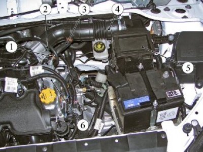
Figure 8-14 - Air cleaner with intake pipe hose assembly: 1 - Upper crankcase ventilation hose clamp; 2 - intake pipe hose clamp; 3 - upper crankcase ventilation hose; 4 - inlet pipe hose; 5 - air filter; 6 - cylinder head cover
Loosen clamp 2 and disconnect hose 4 of the intake pipe from the throttle body (phillips screwdriver).
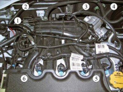
Figure 8-15 - Hoses and tubes to the intake module (for engines 21129 and 21179): 1 - clamp; 2 - brake booster hose; 3 - clamp; 4 - crankcase ventilation tube; 5 - tip of the adsorber valve tube; 6 - intake module
Loosen clamp 1, Figure 8-15, and disconnect brake booster hose 2 from intake module 6 (for cars with H4M engine, press the clamps and disconnect the tip) (phillips screwdriver or 8 mm socket head and ratchet).
Press clamp 3 and disconnect crankcase ventilation tube 4 from the intake module (pliers).
Press the spring clamps and, by moving along the axis of the fitting, disconnect the tip 5 of the adsorber valve tube and the tube itself from the intake module.
Disconnect pipes 1 and 2, Figure 8-16, of the fuel line with the mounting bracket 3 in assembly from the intake module 4 (for cars with engines 21129 and 21179).
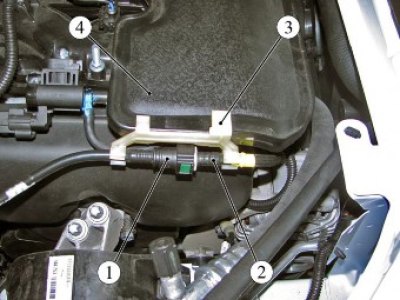
Figure 8-16 - Fastening the fuel pipes (for engines 21129 and 21179): 1 - intermediate fuel line tube; 2 - front fuel line pipe; 3 - Pipeline fastening bracket; 4 - intake module
Disconnect the ignition system wiring harness connectors from the connectors:
- sensor 1, figure 8-17, crankshaft position;
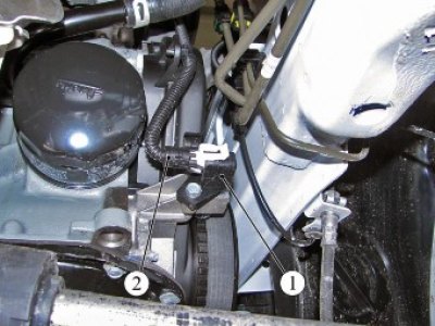
Figure 8-17 - Crankshaft Position Sensor: 1 - crankshaft position sensor; 2 - ignition system wiring harness
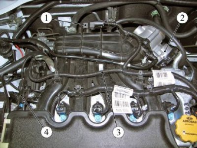
Figure 8-18 - Ignition System Wiring Harness Connections (for engines 21129 and 21179): 1 - air pressure and temperature sensor; 2 - throttle pipe; 3 - ignition system wiring harness; 4 - intake manifold flap valve
- sensor 1, figure 8-18, air pressure and temperature;
- throttle pipe 2;
- valve 4 intake manifold flap (for engine 21129);
Disconnect the ignition system wiring harness clamps from the intake module and move the harness to the side (flat head screwdriver, pliers).
For cars with engines 21129 and 21179
Disconnect the connectors of harness 1, Figure 8-19, wires from ignition coils 4, disconnect clamps 2 from intake module 3 and move the ignition coil harness to the side (pliers).
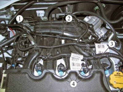
Figure 8-19 - Ignition Coil Wire Harness Connections (for engines 21129 and 21179): 1 - ignition coil wiring harness; 2 - clamp; 3 - intake module; 4 - ignition coil
Unscrew the three nuts and remove the throttle body from the intake module (replacement head 10, ratchet).
Unscrew the two nuts 1, Figure 8-20, securing the intake module 3 to the cylinder head and remove the special washers 2 (replacement head 10, extension, ratchet).
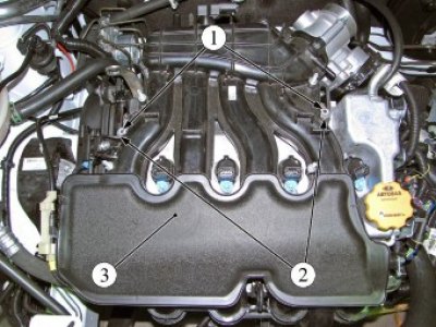
Figure 8-20 - Intake Module Mounting (for engines 21129 and 21179): 1 - intake module mounting nut; 2 - special washer; 3 - intake module
Disconnect the clamp securing the injector wiring harness from the intake module (flat head screwdriver, pliers).
Remove the engine mudguard in accordance with the requirements of TI 3100.25100.20594.
Loosen screw 1, Figure 8-21, securing tube 6 of the oil level indicator guide to the intake module and remove the tube with the oil level indicator assembly (phillips screwdriver).
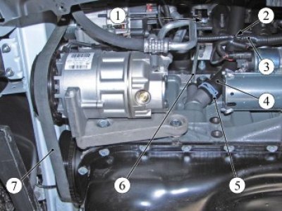
Figure 8-21 - Removing the Intake Module: 1 - screw; 2 - clamp; 3 - wiring harness; 4 - lower crankcase ventilation hose; 5 - clamp; 6 - oil level indicator guide tube; 7 - drive belt for attachments
Cut clamp 2 securing harness 3 wires to hose 4 lower crankcase ventilation (technological knife).
Press clamp 5 and disconnect the lower crankcase ventilation hose from the cylinder block pipe (pliers).
Remove belt 7 of the attachment drive in accordance with the requirements of Section 4 of this technological instruction.
For cars with engines 21129, 21179 with air conditioning system
Unscrew the three bolts 1, Figure 8-22, fastenings, remove the compressor 2 of the air conditioning system without breaking the tightness of the system and hang it on a technological hook (replaceable head 10, ratchet, technological hook).
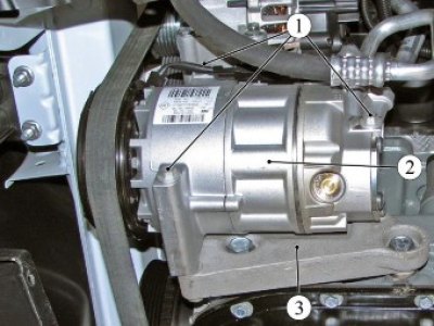
Figure 8-22 - Removing the air conditioning compressor: 1 - bolt; 2 - air conditioning compressor; 3 - bracket for mounted units
For cars with engines 21129 and 21179
Unscrew nut 1, Figure 8-23, fastening and disconnect terminal 2 of the wiring harness from the generator 5 (replacement head 13, extension, ratchet).
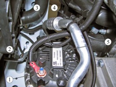
Figure 8-23 - Connecting the wiring harnesses to the generator: 1 - nut; 2 - terminal of the wiring harness to the generator; 3 - wiring harness; 4 - clamp; 5 - generator
Disconnect the 3-wire harness connector from the generator.
Unscrew the four bolts 1, Figure 8-24, fastenings and remove the generator 2 (replacement head 10, ratchet).
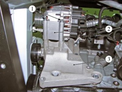
Figure 8-24 - Generator mounting: 1 - bolt; 2 - generator; 3 - bracket for mounted units
Loosen bolt 1, Figure 8-25, securing terminal 2 of the ground wire on bracket 3 of the attachment units and disconnect the terminal (replaceable head 13, ratchet wrench).
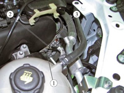
Figure 8-25 - Fastening the ground wire harness terminal to the accessory bracket: 1 - bolt; 2 - terminal of the "ground" wire; 3 - bracket for mounted units
Loosen bolts 1 and 2, Figure 8-26, of the fastening and remove bracket 3 of the mounted units (replaceable head 13, 17, extension, ratchet).
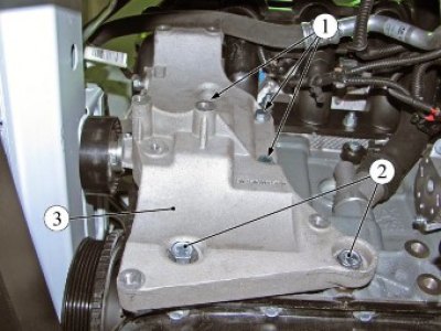
Figure 8-26 - Fastening the ground wire harness terminal to the accessory bracket: 1 - bolt M8; 2 - bolt M10; 3 - bracket for mounted units
Disconnect connector 1, Figure 8-27, of the wiring harness from the 2-phase sensor.
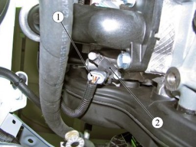
Figure 8-27 - Phase sensor: 1 - Wiring harness connector; 2 - phase sensor
Disconnect the harness clamp from the intake module and move the harness to the side (pliers, flat screwdriver).
Unlock three washers 1, Figure 8-28, locking and unscrew three nuts 3 of the studs securing the additional muffler 2 to the exhaust pipe 5 of the muffler with neutralizer assembly, disconnect the additional muffler from the exhaust pipe of the muffler and remove gasket 4 (flat screwdriver, 10 mm spanner, 10 mm socket, extension and ratchet wrench).
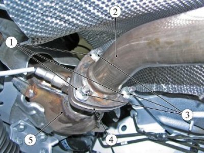
Figure 8-28 - Connecting the additional muffler to the exhaust pipe of the muffler with the neutralizer assembly (for engines 21129 and 21179): 1 - lock washer; 2 - additional muffler; 3 - nut; 4 - muffler flange gasket; 5 - exhaust pipe with neutralizer
Unscrew and remove two bolts 6, Figure 8-29, and bolt 7, remove flat and spring washers and remove bracket 1 of the rear engine mount support with rod 2 and reinforcement 4 as an assembly (replaceable head 18, ratchet).
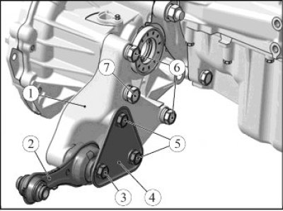
Figure 8-29 - Rear powertrain suspension support: 1 - rear suspension support bracket; 2 - rear suspension support rod; 3 - rod mounting bolt; 4 - amplifier; 5 - amplifier mounting bolt; 6 - bracket mounting bolt; 7 - bracket mounting bolt
Unscrew two bolts 1, Figure 8-30, and three nuts 2 with washers 4 securing the intake module 3 to the cylinder head 5 (replacement head 13, ratchet and extension).
Carefully tilt the engine away from the radiator and remove the intake module.
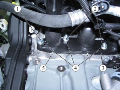
Figure 8-30 - Intake module mounting: 1 - bolt; 2 - nut; 3 - intake module; 4 - washer; 5 - cylinder head
For cars with H4M engine
Loosen the four mounting bolts and remove the throttle body from the intake module and set it aside (replaceable head 8, extension, ratchet).
Remove the two bolts securing the intake module to the cylinder head cover (replacement head 10, extension, ratchet).
Loosen the five bolts securing the intake module on the radiator side and remove the intake module (replacement head 10, extension, ratchet).
Installation
For cars with engines 21129 and 21179
Carefully tilt the engine away from the cooling system radiator and install module 3, Figure 8-30, intake on cylinder head 5. Screw in and tighten two bolts 1 and three nuts 2 with washers 4 to secure the intake module. Tightening torque of bolts and nuts 2.1...2.5 Nm (21...25 kgf·m) (replaceable head 13, ratchet, extension, torque wrench).
Install bracket 1, Figure 8-29, the rear engine mount supports with rod 2 and amplifier 4 in assembly and tighten, without tightening, two mounting bolts 6 with flat and spring washers (replaceable head 18, ratchet).
Tighten bolt 7 with a flat and spring washer. Bolt tightening torque 53...71 Nm (5.3...7.1 kgf·m) (replaceable head 16, ratchet, torque wrench).
Tighten bolts 6 of bracket 1 finally. Tightening torque of bolts 90_120 N·m (9.0_ 12.0 kgf·m) (replaceable head 18, torque wrench).
Attach the rod 2 of the rear suspension support to the front suspension subframe, install the bolt and tighten the fastening nut. Bolt tightening torque 90...120 Nm (9.0...12.0 kgf·m) (replacement head 18, ring spanner 16, ratchet spanner, torque spanner).
Install a new gasket 4 on the flange of the intake pipe 5, Figure 8-28, with the neutralizer assembly, attach the additional muffler 2, install the lock washers 1. Screw in and tighten the three nuts 3 of the studs securing the additional muffler to the intake pipe and lock. Tightening torque of nuts 21...25 Nm (2.1...2.5 kgf·m) (replaceable head 10, ratchet wrench, torque wrench, blunt chisel, hammer).
Connect connector 1, Figure 8-27, of the wiring harness to the 2-phase sensor and the wiring harness fastening clamp to the intake module.
Install bracket 3, Figure 8-26, of the mounted units and secure with bolts. Bolt tightening torque: 1 (M8) - 15...24 Nm (1.5...2.4 kgf·m); 2 (M10) - 33...52 Nm (3.3..5.2 kgf·m) (replaceable head 13, 17, extension, ratchet, torque wrench).
Install terminal 2, figure 8-25, of the ground wire on bracket 3 of the attachments and secure with bolt 1. Bolt tightening torque 18...22 N·m (1.8...2.2 kgf·m) (replaceable head 13, ratchet wrench, torque wrench).
Install generator 2, Figure 8-24, in accordance with the requirements of TI 3100.25100.20597.
For cars with engine 21129 and 21179 with air conditioning system
Install compressor 2, Figure 8-22, of the air conditioning system in accordance with the requirements of TI 3100.25100.20590.
For cars with engine 21129
Install belt 7, Figure 8-21, of the drive of the attachment units in accordance with the requirements of Section 4 of this technological instruction.
Install the lower crankcase ventilation hose 4 onto the cylinder block pipe and secure with clamp 5 (pliers).
Secure the 2 wire harness 3 to the 4 lower crankcase ventilation hose with a new clamp.
Install the oil level indicator guide tube 6 and secure it with screw 1 to the intake module. Tightening torque of screw 3_8 Nm (0.3...0.8 kgf·m) (phillips socket, torque wrench).
Install the engine mudguard in accordance with the requirements of TI 3100.25100.20594.
Install two washers 2, Figure 8-20, screw in and tighten two nuts 1 securing the intake module 3 to the cylinder head. Tightening torque of nuts 3_5 Nm (0.3_0.5 kgf·m) (replacement head 10, ratchet, extension, torque wrench).
Attach the injector wiring harness clamp to the intake module.
Install the throttle body onto the intake module and secure with three nuts. Tightening torque of intake module mounting nuts 5...8 Nm (0.5...0.8 kgf·m) (replaceable head).
Connect the connectors of harness 1, Figure 8-19, wires to ignition coils 4, connect clamps 2 to intake module 3.
Connect the ignition system wiring harness connectors to the sensor and actuator connectors in the reverse order of removal.
Attach the wiring harness clamps to the intake module.
Connect tubes 1 and 2, Figure 8-16, of the fuel line with the mounting bracket 3 as an assembly to the intake module 4.
For cars with H4M engine
Install the intake module on the engine, install, without tightening, the two bolts securing the intake module to the cylinder head cover (replacement head 10, extension, ratchet).
Loosely install the five intake module mounting bolts to the radiator side of the cylinder head (replacement head 10, extension, ratchet).
Tighten the intake module mounting bolts. Tightening torque of bolts 7...15 Nm (0.7...1.5 kgf·m) (replaceable head 10, extension, ratchet, torque wrench).
Install the throttle body onto the intake module and secure with four bolts. Tightening torque of bolts 5...8 Nm (0.5...0.8 kgf·m) (replaceable head 8, extension, ratchet, torque wrench).
For cars of all trim levels
Attach tip 5, Figure 7-13, of the adsorber valve tube by moving it along the axis of the fitting until the spring lock clicks. After installation, check the reliability of the tube fixation.
Install the adsorber valve tube into the fastening elements on the intake module 6.
Connect tube 4, Fig. 8-15, of the crankcase ventilation, hose 2 of the brake booster, hose 4, Fig. 8-14, of the inlet pipe and upper hose 3 of the crankcase ventilation in the reverse order of removal (phillips screwdriver, pliers).
Install the intake module screen.
Connect the ground wire terminal to the battery in accordance with the requirements of TI 3100.25100.20597.
Present the vehicle to the Quality Control Department. The Quality Control Department will check the vehicle for compliance with the requirements of TU 017200-254-00232934, paragraphs 1.19.10, 1.19.14, 1.19.21.3 in the scope of work performed.