
Removing
Place the vehicle on a two-post lift and apply the parking brake (electrohydraulic lift type P-3.2G with a lifting capacity of 3.2 tons).
For vehicles with a body "station wagon"
Tilt the rear row of seats forward (for 5-seater configuration) or middle row (for 7-seater configuration).
Detach and lift upholstery.
Remove the hatch cover of the electric fuel pump.
Disconnect connector 1, Figure 11-35, rear wiring harness from fuel pump module 2.

Figure 11-35 - Disconnecting the rear wiring harness block from the fuel pump module: 1 - block of the rear wiring harness to the fuel pump module; 2 - electric fuel pump module; 3 - fuel tank
Start the engine and let it run at idle until it comes to a complete stop to relieve pressure in the fuel system, ensuring that exhaust gases are removed (exhaust coil with fan type SERF/SP f. "SovPlym"). Switch off the ignition.
Disconnect wire terminal "masses" from the battery.
Connect the block, wiring harness to the fuel pump module.
Install the hatch cover of the electric fuel pump.
Install and secure the floor upholstery.
lower rear (for 5-seater configuration) or medium (for 7-seater configuration) row of seats.
Operations for all vehicle configurations
Detach the right front wheel arch guard fastener.
Move aside the protective cover of the right front wheel arch.
Unscrew bolt 1, Figure 11-36, and nuts 2, remove protective screen 3 of pipelines (interchangeable head 10, extension, crank).
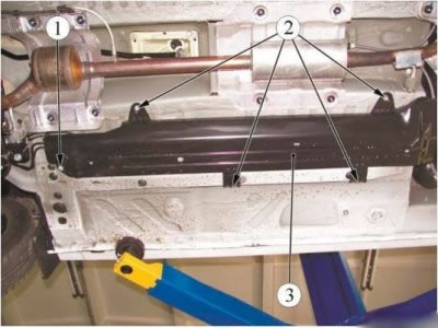
Figure 11-36 - Removing the protective screen of pipelines: 1 - bolt; 2 - nut; 3 - protective screen of pipelines
Press the spring clips of the tube connectors 1 and 2, Figure 11-37, and by moving along the axis of the fittings, disconnect the tubes from the fuel tank 3.
Attention. For vehicles with a body "van" prevent fuel ejection when fuel pipe 2 is disconnected, as the pressure in the fuel line is maintained.
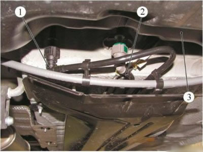
Figure 11-37 - Disconnecting the pipes from the fuel tank: 1 - fuel vapor recovery tube; 2 - fuel tube; 3 - fuel tank
Disconnect the fuel pipe and the fuel vapor recovery pipe from the holders on the bottom of the body.
Disconnect from the canister 1, Figure 11-38, pipe 2 evaporating fuel vapor. Disconnect fuel pipe 1, Figure 11-39, from fuel rail 2.
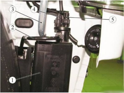
Figure 11-38 - Disconnecting the fuel vapor recovery tube from the canister: 1 - adsorber; 2 - fuel vapor recovery tube; 3 - breather tube; 4 - block of the wiring harness to the canister purge solenoid valve; 5 - adsorber tube
Remove the fuel pipe, the fuel vapor recovery pipe and install technological plugs in the pipe holes.
Installation
Remove technological plugs.
Connect fuel pipe 1, Figure 11-39, to fuel rail 2.
Connect pipe 2, Figure 11-38, for evaporating fuel vapors to canister 1.
Fix the fuel pipe and the fuel vapor recovery pipe in the holders on the bottom of the body.
Connect pipes 1 and 2, Figure 11-37, to the fuel tank 3 by moving along the axis of the fitting until the connector spring lock clicks. Check the tubes are secure.
Install protective screen 3, Figure 11-36, piping, nuts 2 and bolt 1 (interchangeable head 10, extension, crank).
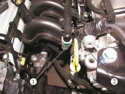
Figure 11-39 - Disconnecting the fuel pipe from the fuel rail: 1 - fuel pipe; 2 - fuel rail
Tightening torques:
- bolt of fastening of the protective screen of pipelines 10 Nm (1.0 kgf·m);
- nut for fastening the protective screen of pipelines 10 Nm (1.0 kgf·m) (interchangeable head 10, extension, torque wrench).
Install the protective cover of the right front wheel arch and fix.
Attach wire terminal "masses" to the battery.