



Disassembly of the fuel module is shown here.
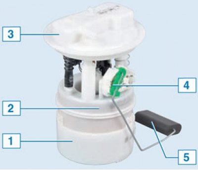
Fuel module: 1 – glass; 2 – fuel filter; 3 – module cover; 4 – fuel level indicator sensor; 5 – float
When to change the fuel pump
The reason for replacing the fuel pump, in addition to its complete failure, is usually a change in the behavior of the car.
The most typical signs of pump failure:
- partial loss of power;
- inadequate response to "gas";
- unstable engine operation at minimum idle speed;
- change in engine tone;
- noise in the fuel tank;
- uncertain engine start.
In all these cases, the culprit is usually mechanical wear of the electric fuel pump parts or burning of its contacts. Sometimes the fuel filter at the inlet simply gets dirty. You can wash it, or better yet, buy a new one and replace it. To perform these operations, it is necessary to remove the fuel module.
Removal
Place the vehicle in the work area and apply the parking brake.
For vehicles with a "station wagon" body
Tilt the rear row of seats forward (for 5-seater configuration) or the middle row (for 7-seater configuration).
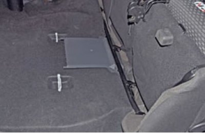
Lift the lid and lift the floor covering.
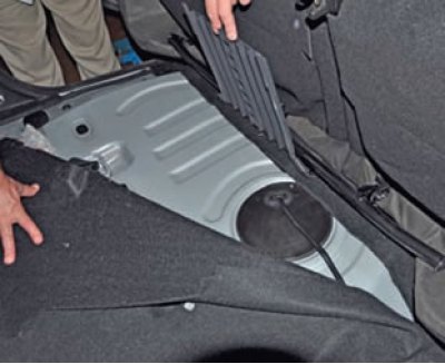
For vehicles with a "van" body
Remove the B-pillar trim on the right side.
Remove the right side of the body partition.
Remove the right front section of the cargo area floor.
Operations for all vehicle configurations
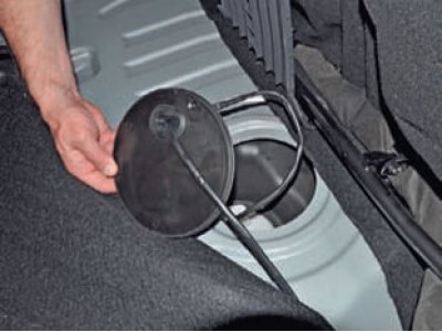
Remove cover 1, Figure 11-26, of the electric fuel pump hatch.
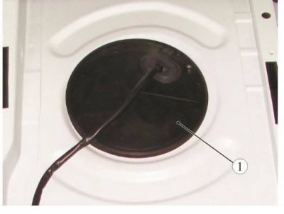
Figure 11-26 - Removing the electric fuel pump hatch cover.
Having pressed the lock with a screwdriver...
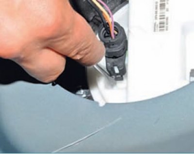
... disconnect connector 1, figure 11-27, of the rear wiring harness from module 2 of the electric fuel pump.
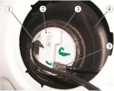
Figure 11-27 - Removing the electric fuel pump module: 1 - rear wiring harness connector to the electric fuel pump module; 2 - electric fuel pump module; 3 - Electric fuel pump module mounting nut; 4 - fuel tank; 5 - fuel line tube
Start the engine and let it run at idle speed until it stops completely to relieve pressure in the fuel system, ensuring the exhaust gases are removed (exhaust coil with a fan of the SERF/SP type from SovPlym). Turn off the ignition.
Disconnect the ground wire terminal from the battery (spanner 10).
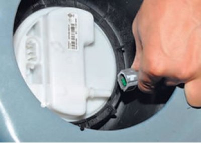
Press the spring clamps of the fuel line tube connector 5 and, by moving it along the axis of the fitting, disconnect the tube from the electric fuel pump module.
Turn nut 3 (pressure ring) fastening the fuel pump module counterclockwise (tool Mot. 1397 or key 67.78129704 L for removing and installing the clamping ring of the electric fuel pump module).
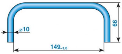
Drawing of a simple device for unscrewing and screwing the clamping ring of the fuel pump module
If there is no device, then unscrew it using a suitable tool, for example a mounting spatula. Resting against the grooves in the body floor panel, we push alternately into different edges around the circumference of the pressure ring. (the same thing needs to be done during assembly)
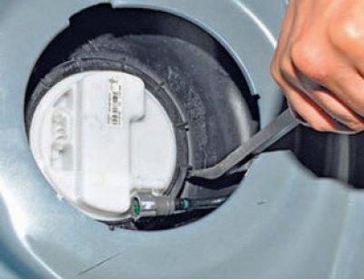
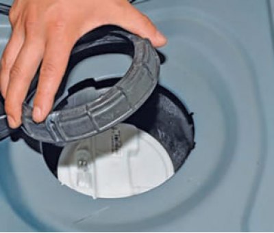
Remove the nut.
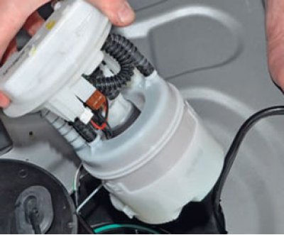
remove the electric fuel pump module, removing the fuel level indicator sensor float from the tank.
Remove the sealing ring.
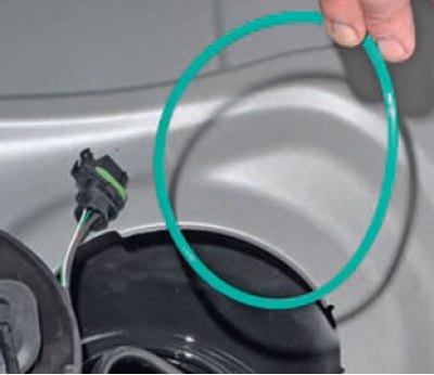
Cover the hole in the fuel tank with thick paper or plastic.
Disassembling the fuel module to replace the pump, filter, or sensor is shown here.
Installation
Note: According to the regulations, the sealing ring and the nut for fastening the electric fuel pump are subject to replacement.
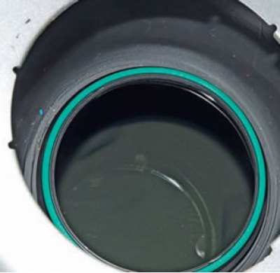
Install a new sealing ring into the groove on the fuel tank.
Install the electric fuel pump module into the fuel tank, aligning marks 1 and 3, Figure 11-28.
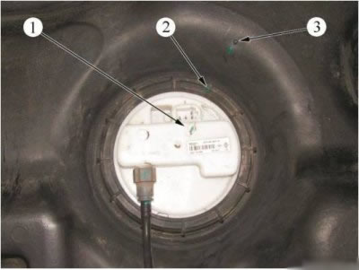
Figure 11-28 - Marks for installing the electric fuel pump module: 1 - mark on the body of the electric fuel pump module; 2 - mark on the body of the nut for fastening the electric fuel pump module; 3 - mark on the fuel tank body
Install a new nut securing the electric fuel pump module and, by hand, press on the electric fuel pump module (to prevent the sealing ring from falling out), screw it clockwise by hand onto the fuel tank.
Install the nut tightening device and tighten the electric fuel pump module mounting nut until mark 2 on the nut is opposite mark 3 on the fuel tank (mot. 1397 tool or 67.7812-9704 L key for removing and installing the electric fuel pump module clamping ring).
Connect tube 5, Figure 11-27, to module 2 of the electric fuel pump by moving it along the axis of the fitting until the spring lock of the connector clicks. Check the reliability of the tube fixation.
Connect connector 1 of the rear wiring harness to the electric fuel pump module.
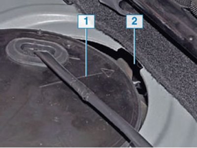
Install the electric fuel pump hatch cover so that arrow 1 on the cover is located opposite groove 2 in the body floor panel.
Further installation should be carried out in the reverse order of removal.
Connect the ground terminal to the battery.