



Removal
Place the vehicle on a two-post lift, apply the parking brake and turn off the ignition.
Set the front wheels to a position that corresponds to the straight-ahead movement of the vehicle.
Remove the front wheels.
Remove the engine crankcase guard.
Remove the lower and side mudguards from the front fenders.
Loosen the three screws securing the lower part of the bumper to the front suspension subframe and remove the lower part of the bumper, releasing the subframe (torx T30 replacement bit, extension, ratchet wrench).
Loosen nut 2, Figure 6-2, of the bolt securing the hinge fork 1 of the intermediate shaft of the steering column to shaft 4 of the steering gear pinion, remove bolt 3 and disconnect the steering shaft from the steering gear pinion shaft (spanner 13).
Loosen the nuts securing the ball joint pins of the outer ends of the steering rods to the steering arms (replaceable head 16, ratchet).
Press the ball joints out of the steering arms (tav. 476 device).
For cars with the K7M engine, disconnect the exhaust pipe from the exhaust manifold and lower it down.
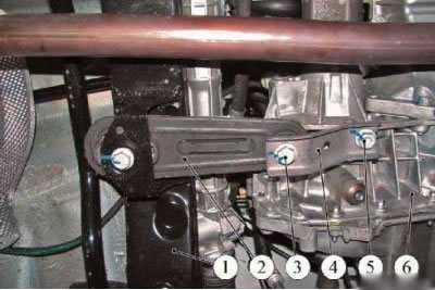
Figure 11-1 - Disconnecting the connecting bracket from the reaction rod: 1 - front suspension subframe; 2 - lower jet thrust; 3 - mounting bolt; 4 - connecting bracket; 5 - mounting bolt; 6 - gearbox housing
Loosen and remove bolt 3, Figure 11-1, securing connecting bracket 4 to lower reaction rod 2 (replacement head 18, extension and ratchet).
Loosen bolt 5 securing the connecting bracket to the gearbox housing 6 and turn bracket 4 away from the reaction rod 2 (replacement head 18, extension and ratchet).
Install transmission stand 3 under the rear part of subframe 2, Figure 11-2, of the front suspension and support the subframe (transmission rack type OMA 604).
Replace the two bolts securing the front of the front suspension subframe with two studs 1 of the powertrain removal tool (replaceable head 18, extension and ratchet, stud driver, studs from the TAV 1747 tool kit).
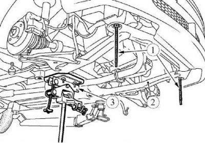
Figure 11-2 - Installing the front suspension subframe removal tools: 1 - studs from the TAV tool kit. 1747; 2 - front suspension subframe; 3 - transmission rack
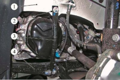
Figure 11-3 - Disconnecting the front suspension subframe connecting rods: 1 - engine compartment side member; 2 - mounting bolt; 3 - subframe stretcher; 4 - front suspension subframe
Loosen and remove bolts 2, Fig. 11-3, securing the struts 3 of the subframe 4 of the front suspension to the side members 1 of the engine compartment (replaceable head 13, ratchet wrench).
Loosen and remove the bolts securing the rear part of the front suspension subframe (replacement head 18, extension and ratchet).
Lower the front suspension subframe to the extent necessary to gain access to the steering mechanism (transmission rack type OMA 604, "Avtospetsoborudovaniye" city of Pskov, TAV. 1747 device).
Install clamps on the low and high pressure lines going to the steering gear (clamp Ms. 583 - 2 pcs.).
For vehicles with K4M engine - unscrew the heat shield mounting bolts and remove the steering gear heat shield (replaceable head 13, ratchet wrench).
Disconnect the high pressure line nipple 1, Fig. 11-4, from the steering gear (spanner 17).
Disconnect the low pressure line nipple 5 from the steering gear (spanner 17).
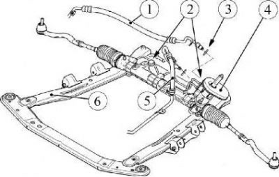
Figure 11-4 - Removing the steering gear: 1 - high pressure pipeline; 2 - steering gear mounting bolts; 3 - sealing ring; 4 - steering mechanism; 5 - low pressure pipeline; 6 - front suspension subframe
Install technological plugs in the steering gear openings and on the pipelines (technological plugs).
For vehicles with a K7M engine, remove the oxygen sensor wiring harness from the holder on the low-pressure pipeline.
Loosen the bolts 2 securing the steering gear to the subframe 6 of the front suspension and remove the mechanism together with the steering rods, moving it to the left (replacement head 18, ratchet wrench).
Installation
Caution: Reuse of the bolt and nut that secure the intermediate shaft pivot fork to the steering gear pinion shaft is not permitted. The bolt and nut must be replaced.
Caution: Re-use of front suspension subframe mounting bolts is not permitted. Bolts must be replaced.
Attention: Before installing pipelines, be sure to replace the sealing rings on the pipeline fittings.
Install the steering gear on the front suspension subframe and secure with bolts. Tightening torque of bolts 105 Nm (10.5 kgf·m) (replaceable head 18, ratchet wrench, torque wrench).
Remove the process plugs from the steering gear openings and high and low pressure pipes.
Install a new sealing ring and connect the high pressure line fitting to the steering gear. Tightening torque of the nipple 21 N·m (2.1 kgf·m) (spanner 17, replaceable insert 17 type 58 21 10 17 f. "Stahlwille", torque wrench type 50 18 00 04 f. "Stahlwille").
Install a new sealing ring and connect the low pressure line fitting to the steering gear. Tightening torque of the nipple 21 Nm (spanner 17, replaceable insert 17 type 58 21 10 17 f. "Stahlwille", torque wrench type 50 18 00 04 f. "Stahlwille").
Remove the clamps from the low and high pressure lines of the power steering system.
For vehicles with a K7M engine, secure the oxygen sensor wiring harness to the holder on the low-pressure pipeline.
For vehicles with K4M engine - install the steering gear heat shield in place and secure with bolts. Tightening torque of bolts 21 Nm (2.1 kgf·m) (replaceable head 13, ratchet wrench, torque wrench).
Raise the front suspension subframe (transmission rack type OMA 604, device TAV. 1747).
Loosen and tighten two new bolts securing the rear portion of the front suspension subframe (replacement head 18, extension and ratchet).
Unscrew the two studs of the powertrain removal tool and screw in, without tightening, two new bolts securing the front part of the front suspension subframe (replaceable head 18, extension and ratchet, stud driver, studs from the TAV 1747 tool kit).
Tighten the subframe mounting bolts according to the diagram.
Install the mounting bolts into the upper holes of the front suspension subframe braces and screw them into the corresponding holes of the engine compartment side members. Tightening torque of bolts 21 Nm (2.1 kgf·m) (replaceable head 13, ratchet wrench, torque wrench).
Connect the gearbox connecting bracket to the lower torque rod of the power unit mount and tighten the bracket mounting bolts to the gearbox housing and to the torque rod. Tightening torque of bolts 105 Nm (10.5 kgf·m) (replacement head 18, extension and ratchet).
For vehicles with a K7M engine, connect the exhaust pipe to the exhaust manifold.
Install the steering column intermediate shaft joint fork onto the steering gear pinion shaft and secure with a new bolt and nut. Nut tightening torque 21 Nm (2.1 kgf·m) (replaceable head 13, ratchet wrench, torque wrench).
Install the ball joint pins of the outer tie rod ends into the holes in the steering arms and secure with the mounting nuts. Tightening torque of nuts 37 Nm (3.7 kgf·m) (replaceable head 16, ratchet, torque wrench).
Secure the lower part of the bumper to the front suspension subframe with three mounting screws (torx T30 replacement bit, extension, ratchet wrench).
Install the lower and side mudguards on the front fenders.
Install the engine crankcase guard.
Install the front wheels.
Fill the power steering pump reservoir with working fluid (power Steering Oil Mobil ATF 52475).
Bleeding the Power Steering System
Caution: To prevent damage to the power steering system, do not hold the steering wheel in extreme positions.
Bleed air from the power steering system, to do this:
- turn the steering wheel several times from one extreme position to the other with the engine off;
- turn the steering wheel several times from one extreme position to the other with the engine running;
- bring the oil level in the tank to normal (power Steering Oil Mobil ATF 52475).
Start the engine and make sure the power steering system is tight; if an oil leak is detected, correct the problem.
Check and, if necessary, adjust the wheel alignment angles.