



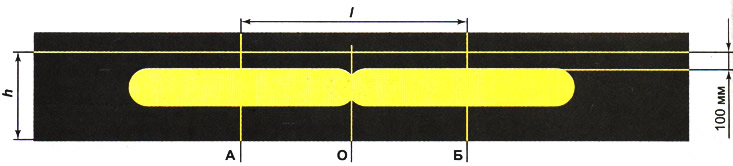
Screen layout diagram for adjusting fog lights: A - vertical line indicating the location of the left fog lamp; B - vertical line indicating the location of the right fog lamp; B - horizontal line indicating the location of the fog lamps; G - a line indicating the height of the upper horizontal boundary of light; O - center line; l - distance between the centers of the fog lamps, h - distance from the surface of the platform on which the car is installed to the fog lamps
Sequence of execution
1. Prepare the car for work (see "Preparing the car for maintenance and repair").
2. If necessary, wash the headlights and wipe dry.
3. We install it fully filled and equipped (spare tire, tool, jack) the car on a flat horizontal surface perpendicular to the selected vertical surface, so that the distance from it to the center of the headlight is 5 m. You can install a 2x1 m plywood sheet in front of the car, subject to the same conditions.
4. Check the tire pressure (see "Checking tire pressure"), if necessary, we bring it up to standard.
5. The assistant sits in the driver's seat (or we lay down the load), after which we vigorously rock the car to adjust the suspension.
6. Mark the screen according to the drawing.
Note: The necessary measurements can be taken using a tape measure.
7. Turn on the fog lights and cover the right one with a sheet of cardboard.
8. Through the hole in the bumper with a long Phillips screwdriver...
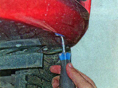
... we rotate the screw of the left headlight, moving its light in the vertical plane, and bring its upper horizontal border to line G.
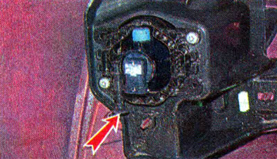
9. Similarly, check and, if necessary, adjust the right fog light.
10. If you cannot adjust the direction of the light, check the installation of the headlight and lamp, and perhaps the bumper. The fog light itself may be faulty, in which case replace it (see "Fog light - removal and installation").