



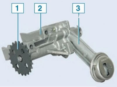
Oil pump Lada Largus: 1 – driven sprocket; 2 – pump body; 3 – pump housing cover with oil receiver
Oil pump in spare parts catalog -[16 cl] [8th grade].
The gear oil pump creates pressure in the lubrication system. It is located at the front in the oil pan and is attached to the cylinder block and is driven by a chain drive from the crankshaft.
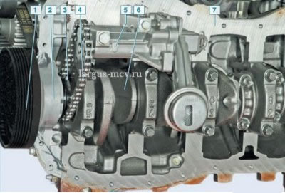
Oil pump drive (oil pan removed): 1 – auxiliary drive pulley; 2 – cylinder block cover; 3 – leading sprocket of pump drive; 4 – drive chain; 5 – oil pump; 6 – crankshaft; 7 – cylinder block
Removal the oil pump
The operation is not complicated and is carried out in a pit or on a lift.
Remove the oil pan.
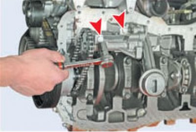
Using a 13 mm socket head, unscrew the two bolts securing the oil pump to the cylinder block (for clarity, shown on a removed engine)…
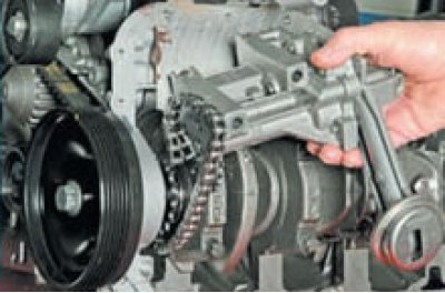
...disengage the pump sprocket from the drive chain and remove the pump.
The principle of operation of oil pumps in cars with internal combustion engines
All production automobile engines are equipped with a pressure lubrication system. The oil pressure in the system is maintained by an oil pump.
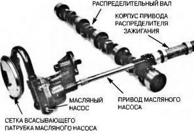
Figure 3.9. In most engines, the oil pump is driven from the distributor drive gear via the intermediate shaft
In most engines equipped with a distributor, the driven gear of the distributor drive is in mesh with the driving gear mounted on the camshaft, as shown in the figure 3.9 The oil pump is driven by an intermediate shaft, often hexagonal in shape, connected to the end of the distributor drive shaft. Some engines use a short shaft to drive the distributor and oil pump, with a gear meshing with the camshaft gear. In this case, the oil pump rotates at half the speed of the crankshaft. In other engines, the oil pump is driven directly from the crankshaft, through a mechanism similar to the automatic transmission pump drive mechanism - in this case, the rotation speed of the oil pump coincides with the rotation speed of the crankshaft. An example of a crankshaft driven oil pump is shown in the figure 3.10-3.12.
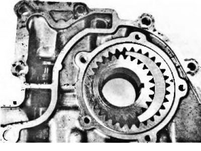
Figure 3.10. Oil pump mounted on the front engine cover. It is driven by the crankshaft
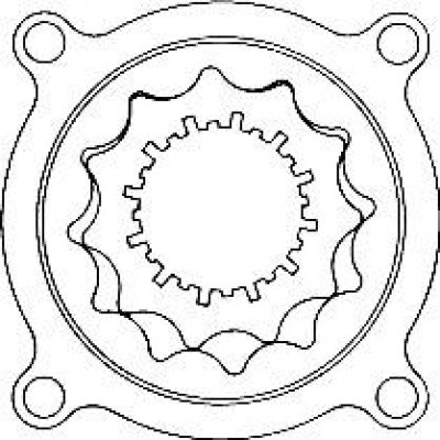
Figure 3.11. Gear-rotor type oil pump driven by crankshaft
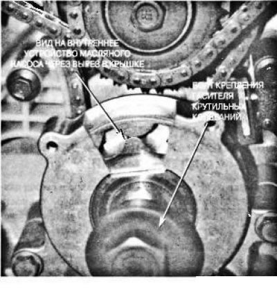
Figure 3.12. Sectional view of the oil pump installed in the V8 engine of the General Motors Northstar. The torsional vibration damper mounting bolt must be tightened to the required tightening torque because it is the clamping force created by this bolt that ensures the operability of the oil pump
In automobile engines, two types of pumps are generally used: gear and rotary (figure 3.13). All oil pumps are positive displacement pumps - with each revolution the pump pumps the same volume of oil. Thus, all the oil that entered the pump is forced out of it. The gear pump consists of two straight-toothed cylindrical gears rotating in a tightly fitted housing. One of the gear wheels is connected to the drive, and the other rotates freely. The gear teeth, when disengaged, move apart, capturing oil entering through the pump inlet channel. The oil is driven along the outer circle of the gear transmission - in the space between the walls of the housing and the teeth of the wheels, as shown in the figure 3.14.
When the teeth mesh again, the oil they have captured is forced into the pump outlet, thus creating pressure in the lubrication system. The rotary oil pump consists of a special gear wheel with petal-shaped teeth, which is engaged with the inner surface of the rotor with petal-shaped recesses. The central gear wheel is connected to the drive, and the rotor surrounding it rotates freely. As the petals move apart, the space between them fills with oil, just like in a gear pump. When the pump rotates, the oil is transferred in a circle between the petals. As the petals come together, oil is forced out of the space between them under pressure, in the same way as in a gear pump. The pump is sized to maintain a pressure of at least 10 psi (70 kPa) in the oil line of a warm, idling engine. As engine speed increases, the pressure will increase by approximately 10 psi for every thousand revolutions per minute, since the engine-driven pump also increases in speed.
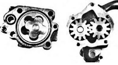
Figure 3.13. Rotary oil pump (trachoidal construction) (left) and gear type (right)
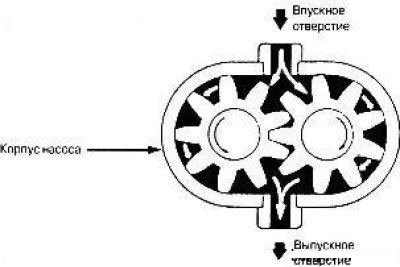
Figure 3.14. In a gear-type oil pump, oil is pumped along the outer circle of the gear transmission. This is an example of a positive displacement pump, all oil entering such a pump is forced out of it