



When replacing fuses and relays, use only fuses and relays of the types recommended for the vehicle and only those manufacturers that have the approval of PJSC AVTOVAZ and are marked in accordance with Tables 1–4.
Attention!
- It is not permitted to use fuses and relays that differ in current rating from those recommended in Tables 1–4. This may result in failures in the vehicle's electrical equipment, short circuits, and vehicle fires.
- A faulty fuse or relay is identified by the failed electrical circuits protected in accordance with Tables 1–4.
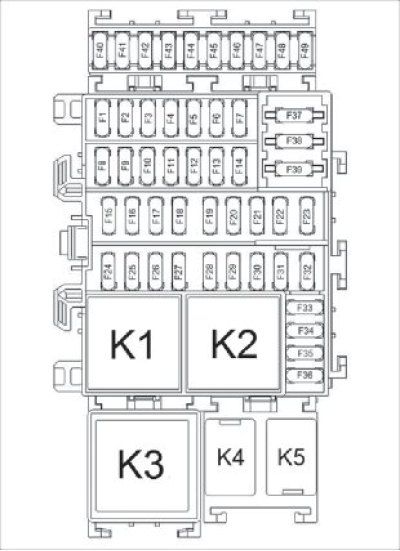
Figure 8.27. Passenger compartment fuse and relay box
Electrical circuits protected by fuses located in the passenger compartment fuse and relay box (Figure 8.27)
Table 1
fuse No | Maximum continuous current, A | Protected electrical circuits |
F1 | 30A | Electric windows front doors |
F2* | 10A | High beam (left headlight) |
F3* | 10A | High beam (headlight right) |
F4* | 10A | Low beam (left headlight) |
F5* | 10A | Low beam (headlight right) |
F6* | 5A | Side lights (headlights left and right) |
F7* | 5A | Side lights (rear lights left and right) |
License plate lights | ||
Headlight corrector switch illumination | ||
Illumination of the central door lock switch | ||
Hazard warning switch illumination | ||
Air conditioning control panel illumination * | ||
Parking Assist Switch Lighting | ||
Driver's door power window switch illumination | ||
Illumination of the electric window switch in the door/passenger doors | ||
Cigarette lighter illumination | ||
Interior lighting unit illumination | ||
Audio/multimedia system illumination | ||
F8 | 30A | Electric rear windows |
Rear electric window lock relay control |
fuse No | Maximum continuous current, A | Protected electrical circuits |
F9* | 7.5A | Rear fog light |
F10 | - | Reserve |
F11 | 20A | Central body electronics unit (side door lock gear motors, trunk lock gear motor) |
F12 | 5A | Immobilizer antenna |
Electronic stability control system controller | ||
Steering wheel angle sensor | ||
Brake light switch | ||
F13 | 10A | Interior lighting unit |
Trunk light | ||
Glove compartment light | ||
SAUKU controller** | ||
Air conditioning control panel ** | ||
F14 ** | 5A | Rain sensor |
F15 | 15A | Windshield and rear window washer |
Central body electronics unit (rear window cleaner) | ||
F16 | 15A | "ERA-GLONASS" system car terminal |
Front seat heaters | ||
Audio system/multimedia system | ||
F17 * | 7.5A | Daytime running lights |
F18 | 7.5A | Brake light bulbs in rear lights |
Additional brake light |
fuse No | Maximum continuous current, A | Protected electrical circuits |
F19 | 5A | Engine Management System Controller |
Central body electronics unit | ||
Additional body electronics unit** | ||
Instrument cluster | ||
Starter Relay Control | ||
Fuel Pump Relay Control | ||
Automatic transmission mode selector | ||
F20 | 5A | Inflatable airbag system control unit |
F21 | 7.5A | Reverse light bulbs |
Automatic Transmission Control Controller | ||
F22 | 5A | Electric power steering pump |
F23 | 5A | Safe Parking System Control Unit |
Electric corrector for left headlight | ||
Electric corrector for right headlight | ||
Headlight corrector switch | ||
Windscreen Heating Relay Control 1 | ||
Windscreen Heating Relay Control 2 | ||
Control of the rear window and outside mirror heating relay | ||
F24 | 15A | Central body electronics unit (power supply of interior fuses F12, F13, F36 with delay after ignition is turned off) |
F25 | 5A | "ERA-GLONASS" system car terminal |
Additional body electronics unit** |
fuse No | Maximum continuous current, A | Protected electrical circuits |
F26 | 15A | Central body electronics unit (direction indicators) |
F27* | 20A | Low beam (headlights left and right) |
F27** | 5A | Low beam headlight switch signal |
High beam headlights on signal | ||
Fog light switch signal | ||
Rear fog light switch signal | ||
F28 | 15A | Sound signal |
Signal for switching on parking lights ** | ||
F29* | 25A | Side lights (headlights and taillights) |
High beam (headlights left and right) | ||
Rear fog light | ||
Horn Relay Control | ||
F30 | - | Reserve |
F31 | 5A | Instrument cluster |
F32 | 7.5A | Central body electronics unit |
"ERA-GLONASS" system car terminal | ||
Audio system/multimedia equipment | ||
Control of the relay for the additional socket in the trunk | ||
Heater Electric Fan Relay Control | ||
Air Conditioner Control Panel* | ||
F33 | 15A | Cigarette lighter |
F34 | 15A | Diagnostic connector |
fuse No | Maximum continuous current, A | Protected electrical circuits |
F34 | 15A | Audio system/multimedia system |
F35 | 5A | Heated exterior mirrors |
F36 | 5A | Electric drive of exterior mirrors |
F37 | 30A | Starter circuit |
F38* | 30A | Windscreen cleaner |
F38** | 30A | Additional body electronics unit (windshield wiper) |
F39* | 40A | Electric heater fan |
F40 | - | Reserve |
F41** | 25A | Additional body electronics unit (daytime running light right headlight, front side lights, low beam left headlight, high beam right headlight) |
F42 | - | Reserve |
F43** | 15A | Additional body electronics unit (power supply for consumers after interior fuse F19) |
F44 | 15A | Socket for additional consumers in the trunk |
F45 | - | Reserve |
F46** | 25A | Additional body electronics unit (interior side lights, fog lights, rear fog light) |
F47** | 25A | Additional body electronics unit (left side daytime running light, rear side lights, right low beam, left high beam) |
* Fuses used only in the "Optima" version (without rain sensor).
** Fuses used only in "Top" and "Luxe" versions (with rain sensor).
Relays located in the passenger compartment fuse and relay box (Figure 8.27)
Table 2
relay No | Maximum continuous current, A | Purpose of the relay |
K1 | 40A | Heater Electric Fan Relay |
K2 | 40A | Rear window and outside mirror heating relay |
KZ | 40A | Rear electric window lock relay |
K4 | - | Reserve |
K5 | 20A | Relay socket for additional consumers in the trunk |
Electrical circuits protected by fuses located in the engine compartment fuse and relay box (Figure 8.28)
Table 3
fuse No | Maximum continuous current, A | Protected electrical circuits |
F1* | 10A | Fog lights |
F2 | 7.5A | Central body electronics unit |
F3 | 25A | Rear window defroster |
Exterior mirror heaters | ||
F4 | 25A | Electronic stability control system controller |
F5 | 70A | Consumers of the on-board electrical system of the cabin |
F6 | 70A | Consumers of the on-board electrical system of the cabin |
fuse No | Maximum continuous current, A | Protected electrical circuits |
F7 | 50A | Electronic stability control system controller |
F8 | 40A | Windscreen heater 1 |
F8 (without heated windshield) | 30A | Socket for additional consumers in the trunk |
F9 | 40A | Windscreen heater 2 |
F9 (without heated windshield) | - | Reserve |
F10 | 30A | Socket for additional consumers in the trunk |
F11 | - | Reserve |
F12 ** | 30A | Starter circuit |
F13 | - | Reserve |
F14** | 25A | Electronic engine management system |
F14 *** | 30A | Electronic engine management system |
F15 | 15A | Air conditioning compressor clutch |
F15 ** (without air conditioning) | 30A | Electric radiator cooling fan |
F16 | 50A | Electric radiator cooling fan |
F17 | 70A | Automatic Transmission Controller (AMT) |
F18 | 80A | Electric power steering pump |
D1 (installed in place of F19) | - | Air conditioning system diode |
fuse No | Maximum continuous current, A | Protected electrical circuits |
D2 (installed in place of F20) | - | Engine Cooling System Diode |
F21 | - | Reserve |
F22 | - | Reserve |
F23** | 15A | Radiator Cooling Fan Relay Control |
Air Conditioner Relay Control | ||
Oxygen sensor 1 | ||
Oxygen sensor 2 | ||
Evaporative Canister Purge Valve | ||
Phase sensor | ||
F23 *** | 7.5A | Oxygen sensor 1 |
Oxygen sensor 2 | ||
Intake Pipe Length Control Valve (only for 21129) | ||
Evaporative Canister Purge Valve | ||
Phase sensor | ||
Phaser valve (only for 21179) | ||
F24 *** | 15A | Engine Management System Controller |
Radiator Electric Fan Control Unit | ||
Ignition coil 1 cylinder | ||
Ignition coil 2 cylinder |
fuse No | Maximum continuous current, A | Protected electrical circuits |
F24 *** | 15A | Ignition coil 3 cylinder |
Ignition coil 4 cylinder | ||
Injector 1 cylinder | ||
Injector 2 cylinder | ||
Injector 3 cylinder | ||
Injector 4 cylinder | ||
Electric fuel pump module with fuel level sensor | ||
F25 *** | 15A | Fuel pump |
* Fuses used only in the "Optima" version (without rain sensor).
** Fuses used in H4Mk engine version only.
*** Fuses used only in versions with engines 21129 and 21179.
Relays located in the engine compartment fuse and relay box (Figure 8.28)
Table 4
relay No | Maximum continuous current, A | Purpose of the relay |
K1 | 20A | Alarm sound relay |
K2 | - | Reserve |
K3** | 40A | Starter relay |
K3* | 20A | Starter relay |
K4 | 40A | Main relay of the ECM |
K5 | 20A | Air Conditioning Compressor Clutch Relay |
K5* (without air conditioning) | 20A | Radiator Cooling Fan Relay |
K6* | 20A | Fuel pump and ignition coil relay |
K6** | 20A | Fuel pump relay |
K7 | 40A | Windscreen Heating Relay 2 |
K7** (without air conditioning) | 40A | Radiator Cooling Fan Relay |
K8 | 40A | Windscreen Heating Relay 1 |
K9 | 20A | Horn relay |
* Relays used in H4Mk engine version only.
** Relays used only in versions with engines 21129 and 21179.
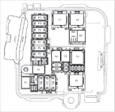
Figure 8.28. Engine compartment fuse and relay box
To access the fuses and relays, remove cover 1 (Figure 8.29), using the notch.
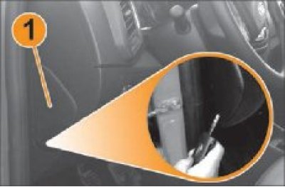
Figure 8.29 Reassembling the interior fuse and relay box cover
Remove the fuse using the tweezers located on the back of the fuse box cover (Figure 8.30).
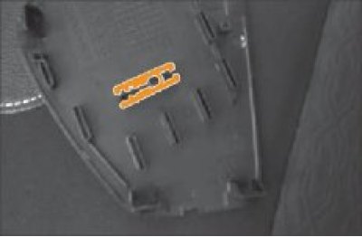
Figure 8.30 Tweezers for removing fuses from the block
To remove the fuse from the tweezers, slide it to the side.