



Fan of the heating, ventilation and air conditioning system unit
The heating, ventilation and air conditioning fan is located in the heating and air conditioning ventilation unit housing on the right side, on the front passenger side.
Place the vehicle in the work area. Open the hood and disconnect the ground wire terminal from the battery (spanner 10).
Remove the instrument panel frame in accordance with the requirements of Section 15 of this TI.
Disconnect connector 4 of wiring harness 1 from fan 2, Figure 15-1, heating, ventilation and air conditioning unit 5.
Press the lock 3 of the fan and at the same time, turn the fan housing counterclockwise to remove the fan from the housing of the ventilation, heating and air conditioning system unit.
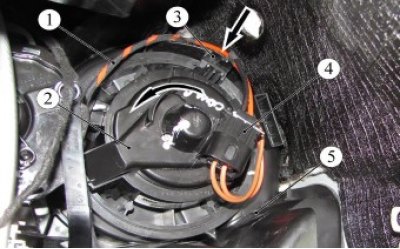
Figure 15-1 - Fan of the heating, ventilation and air conditioning system: 1 - wiring harness for the heating, ventilation and air conditioning unit; 2 - fan of the heating, ventilation and air conditioning unit; 3 - Fan retainer; 4 - HVAC wiring harness connector; 5 - housing of the heating, ventilation and air conditioning system unit
Install the fan of the heating, ventilation and air conditioning system unit in the reverse order of removal, check the functionality.
Fan speed controller for heating, ventilation and air conditioning unit
The fan speed controller for the heating, ventilation and air conditioning system is located in the housing of the heating and air conditioning ventilation unit on the left side, on the driver's side.
Place the vehicle in the work area. Open the hood and disconnect the ground wire terminal from the battery (spanner 10).
Remove the instrument panel in accordance with the requirements of Section 13 of this TI.
Disconnect connector 2, Figure 15-2, of the wiring harness from the fan speed controller (FSC) 1.
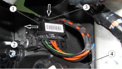
Figure 15-2 - Fan speed controller for heating, ventilation and air conditioning systems: 1 - speed controller (SC); 2 - wiring harness block; 3 - RFV retainer; 4 - housing of the heating, ventilation and air conditioning system unit
Press the lock 3 and, moving the RCHV to the side, remove the RCHV from the housing of the heating, ventilation and air conditioning system.
Install the RCHV in the reverse order of removal.
Radiator of the interior heating system
The heating system radiator is located in the heating and air conditioning ventilation unit housing on the left side, on the driver's side.
Place the vehicle in the work area. Open the hood and disconnect the ground wire terminal from the battery (spanner 10).
Drain the coolant in accordance with the requirements of Section 3, TI 3100.25100.20582.
Remove the instrument panel in accordance with the requirements of Section 13 of this TI.
Remove air duct 2, figure 15-3, driver's foot heating (flat head screwdriver).
Unscrew the two bolts 4 securing the pillar 3 of the instrument panel cross member to the body floor (spanner 13).
Unscrew the two nuts 1 securing the instrument panel crossbar to the crossbar, remove the rack (spanner 13).
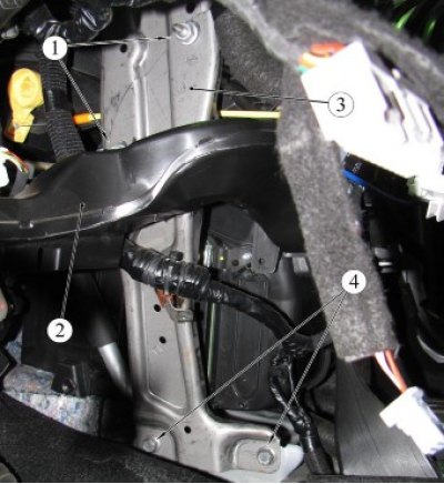
Figure 15-3- Instrument panel cross member: 1 - nut for fastening the rack to the instrument panel crossbar; 2 - driver's foot heating air duct; 3 - Instrument panel crossbar pillar; 4 - bolt for fastening the rack to the body
The heater radiator is connected to the supply and outlet pipes by means of a flange connection through a sealing ring, the connection is fixed with a spring clip.
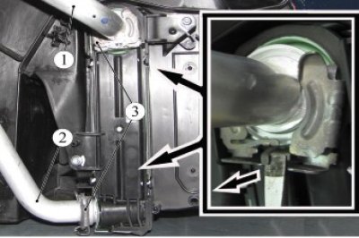
Figure 15-4 - Heater radiator pipes: 1 - heater radiator feed pipe; 2 - heater radiator outlet pipe; 3 - fixing bracket
Pull back the tongue of the clamp stopper 3, Figure 15-4, to fix the connection and at the same time move the clamp, removing it from the connection (flat head screwdriver).
Remove the tube from the heater radiator pipe.
Repeat the operation for the second connection.
Unscrew the two screws 1, Figure 15-5, securing the cover 2 of the radiator 3 of the heater, remove the cover (torx 20 replaceable head, ratchet).
Remove the heater radiator from the HVAC unit housing.
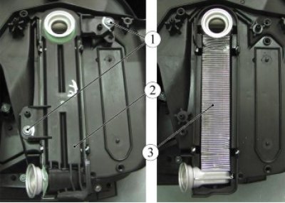
Figure 15-5- Heater radiator cap: 1 - screw for fastening the heater radiator cover; 2 - heater radiator cap; 3 - heater radiator
Install the radiator in the reverse order of removal.
Before installing the inlet and outlet pipes, install new sealing rings.
Fill the engine cooling system with coolant.
Present the vehicle to the Quality Control Department. The Quality Control Department will check the vehicle for compliance with the requirements of this TI and TU 017200-254-0023934 in the scope of work performed.