



Removal
Place the vehicle on the work post and apply the parking brake.
Block the airbag control unit using a diagnostic tool in accordance with the requirements of TI 3100.25100.12044.
Turn off the ignition and disconnect the ground wire terminal from the battery (spanner 10).
Remove the driver airbag module (DAM) in accordance with the requirements of TI 3100.25100.20598.
Set the front wheels to a position that corresponds to the straight-ahead movement of the vehicle.
Remove the steering wheel in accordance with the requirements of paragraph. 2 real TI.
Loosen the two screws securing the steering column covers and, overcoming the force of the clamps, remove the upper and lower steering column covers (torx T20 screwdriver).
Remove the steering column switch assembly with the rotating device in accordance with the requirements of paragraph. 3 real TI.
Remove the transponder receiving coil and the ignition switch in accordance with the requirements of paragraph. 5 real TI.
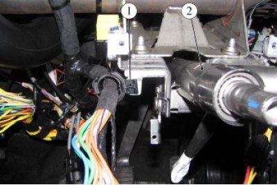
Figure 6-1 - Removing the steering column: 1 - wire harness holder; 2 - steering column
Disconnect the bracket 1, Figure 6-1, of the instrument panel wiring harness from the steering column bracket 2 (flat head screwdriver).
Remove the instrument panel in accordance with the requirements of TI 3100.25100.20599.
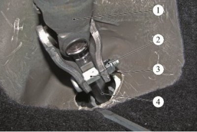
Figure 6-2 - Disconnecting the steering shaft from the steering gear pinion shaft: 1 - intermediate shaft joint of the steering column; 2 - nut of the hinge fork mounting bolt; 3 - hinge fork mounting bolt; 4 - steering gear pinion shaft
Loosen nut 2, Figure 6-2, of the bolt securing the hinge fork 1 of the intermediate shaft of the steering column to shaft 4 of the steering gear pinion, remove bolt 3 and disconnect the steering shaft from the steering gear pinion shaft (spanner 13).
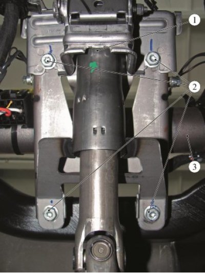
Figure 6-3 - Removing the steering column: 1 - steering column; 2 - steering column mounting bolts; 3 - instrument panel crossbar
Unscrew the four bolts 2, Figure 6-3, securing the steering column to the crossmember bracket 3 of the instrument panel and remove the steering column 1 (replacement head 13, extension and ratchet).
Installation
Caution: Reuse of the bolt and nut that secure the intermediate shaft pivot fork to the steering gear pinion shaft is not permitted. The bolt and nut must be replaced.
Caution: The screw that secures the ignition switch to the steering column must not be reused. The screw must be replaced.
Caution: Re-use of the steering wheel mounting bolt to the steering shaft is not permitted. The bolt must be replaced.
Install the steering column in place and secure it with four bolts to the instrument panel cross member bracket. Tightening torque of bolts 21 Nm (2.1 kgf·m) (replaceable head 13, extension and ratchet, torque wrench).
Install the steering column intermediate shaft joint fork onto the steering gear pinion shaft and secure with a new bolt and nut. Nut tightening torque 21 Nm (2.1 kgf·m) (replaceable head 13, ratchet wrench, torque wrench).
Install the instrument panel in accordance with the requirements of TI 3100.25100.20599.
Secure the instrument panel wiring harness bracket to the steering column bracket (flat head screwdriver).
Install the transponder receiving coil and ignition switch in accordance with the requirements of paragraph. 5 real TI.
Install the steering column switch unit with a rotating device in accordance with the requirements of paragraph. 3 real TI.
Install the upper and lower steering column covers and secure with two screws (torx T20 screwdriver).
(Data taken from the specified website: LADAMAN.ru)
Install the steering wheel in accordance with the requirements of paragraph. 2 real TI.
Install the driver airbag module (DAM) in accordance with the requirements of TI 3100.25100.20598.
Connect the ground wire terminal to the battery and turn on the ignition (spanner 10).
Unlock the airbag control unit using a diagnostic tool in accordance with the requirements of TI 3100.25100.12044.
Check the operation of the steering column switches.
Check the operation of the rotating device, for which:
- turn the steering wheel to the extreme left position;
- turn the steering wheel to the extreme right position;
- return the steering wheel to the center position;
- make sure that there is no fault message displayed on the instrument cluster. Present the vehicle to the Quality Control Department. The Quality Control Department will check the vehicle for compliance with the requirements of TU 017200-254-00232934, paragraphs 1.19.20, 1.19.21 in the scope of work performed.