
The central electrode is installed in the insulator channel having a variable diameter. The electrode head rests on the conical surface of the insulator channel at the point of transition from a larger diameter to a smaller one. The working part of the central electrode protrudes from the insulator by 1.0 to 5.0 mm. The fixing of the electrode in the channel of the insulator and the sealing of this connection is carried out using glass sealant. It is a mixture of special technical glass and metal powder. Glass must have a thermal expansion coefficient equal to that of ceramics. In this case, the sealing plug will not be destroyed by temperature changes during operation. mogall powder (copper or lead) added to glass to make it electrically conductive.
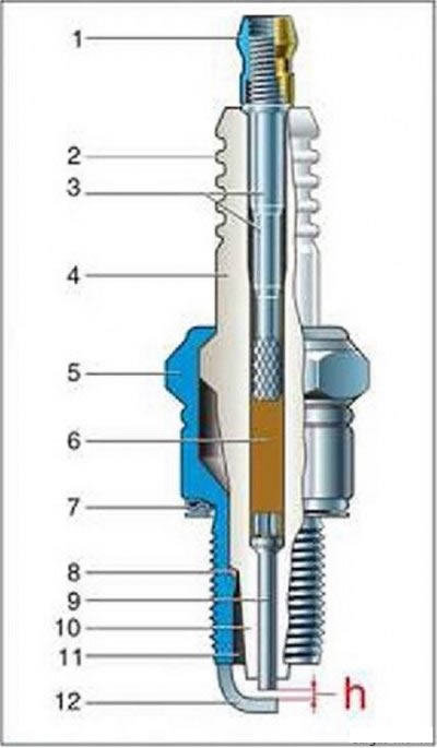
Pic. 9 - Spark plug device: 1 - contact nut: 2 - insulator fins (duck current barriers): 3 - contact rod: 4 - ceramic insulator: 5 - metal case, b - glass sealant plug. 7 - sealing peg: 8 - heat sink washer: 9 - central electrode. 10 - thermal cone of the insulator: 11 - working chamber: 12 side electrode -ground-: h - spark gap
Core Assembly (insulator assembly with central electrode and contact rod) carried out in the following order. The electrode is installed in the channel of the insulator and a powdered glass sealant is poured on top or placed in the form of a tablet. Then, a contact head is installed in the channel of the insulator. Before pressing, the glass sealant occupies a larger volume than after this operation, and the contact rod cannot fully enter the insulator channel. It protrudes above the insulator by about a third of the length. The workpiece is heated to a temperature of 700-900 "With and with a force of several tens of kilograms, the contact rod is introduced into the glass sealant softened under the influence of temperature. At the same time, it flows into the gaps between the channel of the insulator, the head of the central electrode and the contact head. After cooling, the glass sealant solidifies and securely fixes both parts in the insulator channel Between the ends of the electrode and the contact head, a sealing plug is formed with a height of 1.5 to 7.0 mm, completely blocking the insulator channel from gas breakthrough
If it is necessary to build an electrical resistance into the circuit of the central electrode, a resistive glass sealant is used to suppress electromagnetic interference. After cooling, the sealing plug acquires the electrical resistance of the required value.
The core is installed in the candle body so that it comes into contact with its conical surface with the corresponding surface inside the body. Between these surfaces, a sealing-heat-removing» puck (copper or steel).
The fixing of the core is carried out by rolling the shoulder of the housing onto the belt of the insulator. Sealing at the connection insulator - housing is carried out by upsetting the housing in a heated state (thermosetting).
Ground electrode» rectangular section is welded to the end of the body and bent towards the central one. An o-ring is installed on the base of the housing with an emphasis on a flat supporting surface, designed to seal the connection between the spark plug and the engine.
A contact nut is installed on the threaded part of the contact rod, if required by the design of the high-voltage wire tip. In some candles, the contact rod does not have a threaded head, it is immediately stamped in the form of a contact nut.
Insulator
To ensure uninterrupted sparking, the insulator must have the necessary dielectric strength even at high operating temperatures. The voltage applied to the insulator during engine operation is equal to the breakdown voltage of the spark gap. This voltage increases with increasing pressure and gap size and decreases with increasing temperature. On engines with a classic ignition system, spark plugs with a spark gap of 0.5-0.7 mm are used. The maximum breakdown voltage under these conditions does not exceed 12-15 kV (amplitude value). On engines with electronic ignition systems, the installation spark gap is 0.8-1.0 mm. During operation, it can increase to 1.3-1.5 mm (both systems). In this case, the breakdown voltage can reach 20-25 kV.
The design of the insulator is relatively simple - it is a cylinder with an axial hole for installing the central electrode.
in the middle part of the insulator there is a thickening, the so-called "belt" for connection with the body. Below the girdle is a thinner cylindrical part - -dulce-, turning into a thermal cone. At the transition point from the neck to the thermal cone, there is a conical surface intended for installation between the insulator and the body of the heat-removing sealing washer. Above the girdle is located -head', and at the transition point from the girdle to the head there is a shoulder for rolling the body shoulder when assembling the candle.
Permissible, taking into account the safety factor, the wall thickness is determined by the dielectric strength of the insulator material. According to domestic standards, the insulator must withstand a test voltage of 18 to 22 kV (effective value), which is 1.4 times greater than the amplitude The length of the insulator head is determined by the surface overlap voltage and is performed in the range from 15 to 35 mm. For most automotive candles, this value is about 25 mm. A further increase is ineffective and leads to a decrease in the mechanical strength of the insulator. To exclude the possibility of electrical breakdown along the surface of the insulator, its head is provided with annular grooves (current barriers) and covered with a special glaze to protect against possible contamination.
The function of protection against surface overlap on the side of the combustion chamber is performed by a thermal cone. This most important part of the insulator, with relatively small dimensions, withstands the above voltage without overlapping on the surface.
Initially, ordinary porcelain was used as an insulator material. but such an insulator poorly resisted thermal effects and had low mechanical strength.
With an increase in engine power, more reliable insulators were required. than porcelain. Mica insulators have been used for a long time. However, when using lead-added fuels, the mica was destroyed. Insulators were again made of ceramic, but not from porcelain, but from especially durable technical ceramics.
The most common and cost-effective for the production of insulators is the isostatic pressing technology, when granules of the required composition and physical properties are made from pre-prepared components. Preforms of insulators are pressed from granules at high pressure, ground to the required dimensions, taking into account shrinkage during firing, and then fired once.
Modern insulators are made from high alumina structural ceramics based on alumina. Such ceramics, containing about 95% alumina, are able to withstand temperatures up to 1600 'C and have high electrical and mechanical strength.
The most important advantage of alumina ceramic is that it has a high thermal conductivity. This significantly improves the thermal characteristic of the candle, since the main heat flow passes through the insulator, entering the candle through the thermal cone and the central electrode (pic. 10).
Frame
The metal housing is designed to install a spark plug in the engine and ensures tightness of the connection with the insulator. A side electrode is welded to its end, and in designs with an annular spark gap, the body directly performs the function of an electrode «masses».
The body is made by stamping or turning from structural low-carbon steels.
inside the housing there is an annular protrusion with a conical surface. on which the insulator rests. An annular groove is made on the cylindrical part of the body, the so-called thermosetting groove. In the process of assembling the candle, the upper shoulder of the body is rolled onto the insulator belt. Then it is heated and deposited on a press, while the thermosetting groove is subjected to plastic deformation, and the body tightly covers the insulator. As a result of thermal precipitation, the body is in a stressed state, which ensures the tightness of the candle for the entire service life.
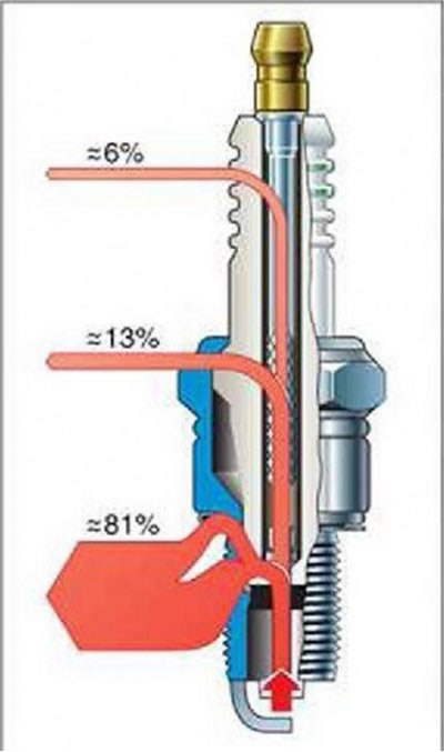
Pic. 10. Heat fluxes in the candle insulator
Electrodes
As mentioned above, in order to improve the ignition efficiency, the electrodes of the spark plug should be as thin and long as possible, and the spark gap should have the maximum allowable value. On the other hand, to ensure durability, the electrodes must be sufficiently massive.
Therefore, depending on the requirements for power, fuel efficiency and toxicity of engines, on the one hand, and the requirements for the durability of the spark plug, on the other hand, a separate design of electrodes was developed for each type of engine.
The appearance of bimetallic electrodes made it possible to solve this problem to a certain extent, since such an electrode has sufficient thermal conductivity. Unlike the usual «monometallic» when working on the engine, it has a lower temperature and, accordingly, a longer resource. In cases where it is required to increase the resource, two electrodes are used "masses- (fig.11). On foreign-made candles, three or even four electrodes are used for this purpose. The domestic industry produces candles with such a number of electrodes only for aviation and industrial gas engines. It should be noted that with an increase in the number of electrodes, the resistance to carbon deposits decreases and cleaning from carbon deposits becomes more difficult.
The following requirements are imposed on the electrode material: high corrosion and erosion resistance: heat resistance and scale resistance: high thermal conductivity; plasticity sufficient for stamping. The cost of the material should not be high. The most widespread in the domestic industry for the manufacture of central electrodes of spark plugs are heat-resistant alloys: iron-chromium-titanium, nickel-chromium-iron and nickel-chromium with various alloying additives
Pic. 11. Candle A26DV-1 with two side electrodes «masses»
Side electrode «masses» should have high heat resistance and corrosion resistance. It must have good weldability with conventional structural steel from which the case is made, therefore, a nickel-manganese alloy is used (For example. NMC-5). The side electrode must have good ductility in order to be able to control the spark gap.
In order to reduce the damping effect of the electrodes, when refining the candles, grooves are made on the electrodes, and masses are made in the electrode» make through holes. Sometimes the side electrode is divided into two parts, turning a single-electrode candle into a two-electrode one.
Built-in resistor
A spark discharge is a source of electromagnetic interference, including radio reception. To suppress them, a resistor is installed between the central electrode and the contact head, having an electrical resistance of 4 to 13 kOhm at a temperature of 25±10°C. During operation, it is allowed to change the value of this resistance in the range of 2-50 kOhm after exposure to temperatures from -40 to +300°C and high voltage pulses.
Additional insulator
Even small losses of ignition energy lead to a weakening of the spark with all the unpleasant consequences: start-up deterioration, unstable idling, loss of engine power, excessive fuel consumption, increased exhaust gas toxicity, etc. If the surface of the insulator is covered with soot, dirt or just moisture, leakage occurs «to ground». It is detected in the dark in the form of a corona discharge on the surface of the insulator. Leakage through the contaminated surface of the thermal cone of the insulator in the combustion chamber of the engine can lead to a failure in sparking. The most radical way to increase the electrical strength of the insulation is to install an additional insulator in the form of a ceramic bushing between the body and the contact head of the candle. Thus, the candle acquires double protection against current leakage «to ground».
Pre-chamber candles
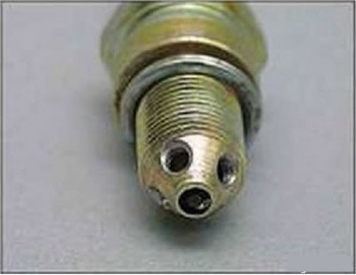
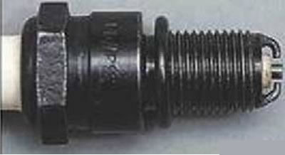
Pic. 12. Pre-chamber spark plug
There are various versions of the candle device, in which the working chamber is made in the form of a prechamber. They are used to improve the combustion of the working mixture. Pre-chamber spark plugs are similar to spark plugs for forced sports engines, where the electrodes for protection against overheating are installed deep inside the working chamber of the body. The difference is. that hole. connecting the working chamber (prechamber) with the engine cylinder, make a special shape. When compressed, the fresh mixture enters the prechamber, a spark discharge occurs in the region of the vortex flow, and the formation of the primary ignition site becomes more intense. This ensures rapid propagation of the flame in the prechamber. The pressure rises rapidly and throws out a flame that penetrates the engine combustion chamber and intensifies the ignition of even a very lean working mixture.
When burning gases flow from the prechamber into the engine cylinder, due to the turbulence of the combustible mixture, the combustion process is accelerated and becomes more efficient. This. in turn, can lead to an improvement in indicators characterizing fuel efficiency and exhaust gas toxicity.
The disadvantages of pre-chamber candles are that the damping effect of the electrodes is great, and the resistance to carbon deposits is low. Ventilation of the prechamber is difficult and the combustible mixture in it contains an increased amount of residual gases. When burning gases flow from the prechamber into the cylinder, additional heat losses occur. One of the variants of the pre-chamber candle is shown in Fig. 12.