



Removal
Place the vehicle on a two-post lift and turn off the ignition (electro-hydraulic lift type P-3.2G with a lifting capacity of 3.2 t).
Remove the rear wheels in accordance with the requirements of Section 14 of this TI.
Remove the rear wheel speed sensor wiring harnesses from the holders on the rear suspension arms.
Loosen the bolts securing the speed sensors to the rear brake shields and remove the sensors (torx T30 replacement bit, extension, ratchet wrench).
In accordance with the requirements of TI 3100.25100.20596:
- remove the hand brake cables from the holders on the rear suspension arms;
- remove brake drums;
- disconnect the hand brake cables from the brake shoe drive levers and remove the cable end from the holes in the brake shields;
- disconnect the brake pipes from the flexible brake hoses, the brake hoses should remain on the rear suspension arms.
Disconnect the shock absorbers from the rear suspension arms and remove the springs in accordance with the requirements of Sections 8 and 9 of this TI.
Install a transmission stand (transmission stand type OMA 604, "Avtospetsoborudovaniye") under the center of the rear suspension arm beam.
Loosen the nuts securing the rear suspension arms to the brackets, lower the transmission rack and remove the rear suspension arms from the vehicle. The operation is to be performed by two performers (replacement head 18, extension and ratchet).
Replacement of rubber-metal hinges
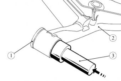
Figure 13-1 - Marking the location of the hinge in the rear suspension arm: M1 - mark on the rear suspension arm; M2 - mark on the hinge body
Attention: Before removing the rubber-metal hinge, it is necessary to mark its orientation in the hole of the rear suspension arm:
- make marks "M1" and "M2" on the rear suspension arm and hinge;
- copy the "M2" mark to the new hinge.
Note: Marking the joints is necessary for correct installation and to prevent premature wear of the rear suspension arm joints, as well as to ensure reliable vehicle control.
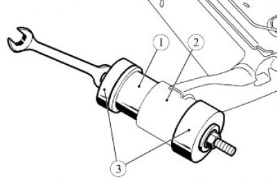
Figure 13-2 - Pressing out the hinge: 1 - rear suspension arm joint; 2 - rear suspension arm; 3 - mandrel for pressing out from the Tar. 1838 set
Press out the rubber-metal hinge from the rear suspension arm (pressing mandrel from Tar. 1838 set, hammer).
Install the new rubber-metal joint 1, Figure 13-3, into the hole in the rear suspension arm 2 and align the marks "M1" and "M2", Figure 13-1.
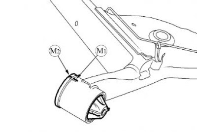
Figure 13-3 - Pressing in the joint: 1 - rear suspension arm joint; 2 - rear suspension arm; 3 - pressing device from Tar. 1838 set
Install tool 3, Figure 13-3, on the joint for pressing and press the joint into the rear suspension arm (pressing device from the Tar. 1838 set, ring spanner 17 - 2 pcs.).
Perform operations to replace the joint for the second lever.
Installation
Install the rear suspension arms onto the transmission stand and position them under the vehicle opposite the mounting points. The operation is to be performed by two performers (transmission rack type OMA 604, "Avtospetsoborudovanie", Pskov).
Install the rear suspension arms into the mounting brackets on the body, insert the bolts and tighten the nuts without tightening them (ring spanner 18, replaceable head 18, ratchet).
Install the springs and connect the shock absorbers to the rear suspension arms in accordance with the requirements of Sections 8 and 9 of this TI.
In accordance with the requirements of TI 3100.25100.20596:
- install the hand brake cables into the holders on the rear suspension arms;
- install the ends of the hand brake cables into the holes in the brake shields and connect them to the brake shoe drive levers;
- install brake drums;
- connect the brake pipes to the flexible brake hoses on the rear suspension arms.
Install the speed sensors into the holes in the brake shields and secure them with bolts. Tightening torque of bolts 14 Nm (1.4 kgf·m) (torx T30 replacement bit, extension, ratchet wrench, torque wrench).
Install the rear wheel speed sensor wire harnesses into the holders on the rear suspension arms.
Bleed the brake system and, if necessary, the clutch hydraulic drive in accordance with the requirements of TI 3100.25100.08020.
Install the rear wheels in accordance with the requirements of Section 14 of this TI.
Place the vehicle on a four-post lift, apply the parking brake and turn off the ignition (four-post platform lift type P-178D-03 with a lifting capacity of 3.5 tons).
Press the rear suspension two or three times with your hands.
Finally tighten the nut of the rear suspension arm mounting bolt to the mounting bracket. Nut tightening torque 125 Nm (12.5 kgf·m) (ring spanner 18, replaceable head 18, torque wrench).
Check the efficiency of the service brake system in accordance with the requirements of TI 3100.25100.13062.
Present the vehicle to the Quality Control Department. The Quality Control Department will check the vehicle for compliance with the requirements of TU 017200-254-00232934, paragraphs 1.19.19, 1.19.22 in the scope of work performed.