



Removal
Place the vehicle on a two-post lift, apply the parking brake and turn off the ignition (electro-hydraulic lift type P-3.2G with a lifting capacity of 3.2 t).
Remove the rear wheels in accordance with the requirements of Section 14 of this TI.
Remove the rear wheel speed sensors in accordance with the requirements of TI 3100.25100.20596.
Release the hand brake lever.
In accordance with the requirements of TI 3100.25100.20596:
- disconnect the hand brake cables from the equalizer, release the cable sheaths from the mounting brackets to the bottom of the vehicle body, to the gas tank and fuel line, remove the ends of the cable sheaths from the holes in the floor tunnel;
- disconnect the brake pipes from the flexible brake hoses, the brake hoses should remain on the rear suspension arms.
If necessary:
- remove the brake system components from the rear suspension arms in accordance with the requirements of TI 3100.25100.20596;
- remove the rear wheel hub axles and brake shields assembled with brake shoes and wheel cylinders in accordance with the requirements of Section 11 of this TI.
Disconnect the shock absorbers from the rear suspension arms and remove the springs in accordance with the requirements of Sections 8 and 9 of this TI.
Install a transmission stand under the center of the rear suspension arm beam (transmission stand type OMA 604, "Avtospetsoborudovanie", Pskov).
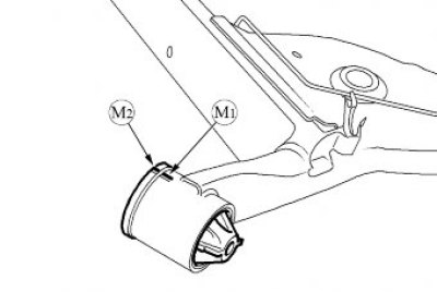
Figure 13-1 - Removing the rear suspension arms: 1 - bracket mounting bolts; 2 - rear suspension arms; 3 - rear suspension arm mounting bracket; 4 - rear suspension arm mounting bolt
Loosen bolts 1, Figure 13-1, securing brackets 3 of the rear suspension arms to the body, lower the transmission rack and remove arms 2 of the rear suspension from the vehicle. The operation is to be performed by two performers (replacement head 18, extension and ratchet).
If necessary:
- unscrew the nuts of the bolts 4 securing the rear suspension arms to the brackets, remove the bolts and remove the brackets (ring spanner 18, replaceable head 18, ratchet);
- replace rubber-metal hinges in accordance with the requirements of paragraph. 14 of this TI.
Installation
Caution: Re-use of shock absorber mounting bolts to rear suspension arms is not permitted. Bolts must be replaced.
Caution: Re-use of the rear suspension arm mounting bolts to the brackets is not permitted. Bolts must be replaced.
Install the brackets for fastening the rear suspension arms to the body, insert new mounting bolts and tighten the nuts without tightening them (ring spanner 18, replaceable head 18, ratchet).
Install the rear suspension arms complete with mounting brackets on the transmission rack and position them under the vehicle opposite the mounting points. The operation is to be performed by two performers (transmission rack type OMA 604, "Avtospetsoborudovanie", Pskov).
Align the mounting tabs of the rear suspension arms opposite the centering holes and tighten the mounting bolts starting from the left bracket. The operation must be performed by two people. Tightening torque of bolts 105 Nm (10.5 kgf·m) (replaceable head 18, ratchet, torque wrench).
Install the rear suspension springs and shock absorbers in accordance with the requirements of Sections 8 and 9 of this TI.
If it was removed:
- install brake shields assembled with brake shoes and wheel cylinders and rear wheel hub axles in accordance with the requirements of Section 11 of this TI;
- install and connect the brake system components: brake pipes, flexible brake hoses, hand brake cables and rear wheel brake drums in accordance with the requirements of TI 3100.25100.20596.
In accordance with the requirements of TI 3100.25100.20596:
- install the hand brake cables into the mounting brackets on the underbody of the vehicle, on the fuel tank and fuel line, install the cable sheath ends into the holes in the floor tunnel, connect the cable ends to the equalizer and adjust the parking brake;
- connect the brake pipes to the flexible brake hoses on the rear suspension arms;
- install rear wheel speed sensors.
Bleed the brake system in accordance with the requirements of TI 3100.25100.08020.
Install the rear wheels in accordance with the requirements of Section 14 of this TI.
Place the vehicle on a four-post lift, apply the parking brake and turn off the ignition (four-post platform lift type P-178D-03 with a lifting capacity of 3.5 tons).
Press the rear suspension two or three times with your hands.
Finally tighten the nut of the rear suspension arm mounting bolt to the mounting bracket. Nut tightening torque 125 Nm (12.5 kgf·m) (ring spanner 18, replaceable head 18, torque wrench).
Check the efficiency of the service brake system in accordance with the requirements of TI 3100.25100.13062.
Present the vehicle to the Quality Control Department. The Quality Control Department will check the vehicle for compliance with the requirements of TU 017200-254-00232934, paragraphs 1.19.19, 1.19.22 in the scope of work performed.