



- removal without loops (when replacing a door);
- removal with loops (allows you to save the original settings)
Place the vehicle in the work area. Open the door and lower the window, disconnect the negative terminal from the battery (spanner 10).
Removal and installation:
Disconnect the harness connector 9, Figure 3-1, of the door 1 wires from the instrument panel harness connector.
Remove the protective tube 6 of the wiring harness, and then the harness itself from the hole in the body pillar.
Loosen screw 4 securing the door stop to the body pillar (torx T40 replaceable head, ratchet).
Unscrew bolts 3 and 8 securing the door to hinges 2 and 7, remove the door assembly (torx T40 replaceable head, ratchet or spanner 13).Perform the operation with an assistant.
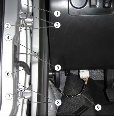
Figure 3-1 - Removing and installing the front door: 1 - front door; 2 - upper door hinge; 3, 8 - door mounting bolt; 4 - screw for fastening the door opening limiter; 5 - door opening limiter; 6 - door harness protective tube; 7 - lower door hinge; 9 - door wiring harness
Install the door in the reverse order of removal. When installing, ensure that the gaps with adjacent surfaces around the perimeter of the door are uniform.
Disassembly/assembly:
Lower the door glass.
Remove trim 3, Figure 3-2, by pulling the upper corner away from the door, overcoming the resistance of the plastic holder.
Remove the trim of the handle 1 trim 4 door (flat head screwdriver).
Unscrew the 2 screws securing the trim (torx T20 replaceable head, ratchet, extension).
Overcoming the resistance of the holders, detach the trim from the door (flat head screwdriver).
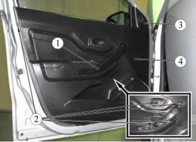
Figure 3-2 - Fastening the front door trim: 1 - Front door trim handle; 2 - door trim fastening screw; 3 - interior exterior mirror trim; 4 - door trim.
Release the clamps of the tip 1, figure 3-3, clip, cable 2 of the inner handle of the lock drive, disconnect the cable from the handle (flat head screwdriver).
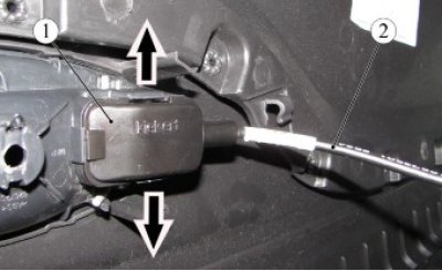
Figure 3-3 - Disconnecting the lock drive rod: 1 - end of the inner handle cable clip of the lock drive; 2 - cable of the inner handle of the lock drive
Disconnect the door wire harness connector from the power window switch assembly or the right door power window switch.
Disconnect the connector of harness 4, Figure 3-4, door wires from harness 3 of the outside mirror wires.
Loosen the 2 screws securing the outside mirror to the door and remove the mirror (replaceable head 8 or Torx T20, ratchet).
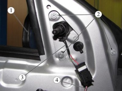
Figure 3-4 - Mounting the outside mirror: 1 - outside mirror; 2 - mirror mounting screws; 3 - mirror wiring harness; 4 - door wiring harness
Grasp the edge of the outer 1, Figure 3-5, horizontal seal of the lowering glass and, pulling upwards, remove the seal from the door panel (flat head screwdriver).
Remove the inner 2 horizontal seal from the door panel, similar to removing the outer seal (flat head screwdriver).
Remove seal 3 of the door frame of the drop glass (flat head screwdriver).
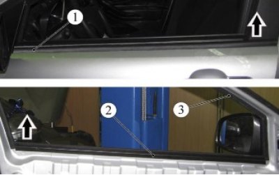
Figure 3-5 - Window door seals: 1 - external horizontal seal of the door glass; 2 - internal horizontal seal of the door glass; 3 - seal of the sliding glass door frame.
Remove the sealing film 2, Figure 3-6, if necessary, use a burner with hot air supply to the place where the mastic is applied (technological knife).
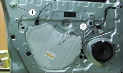
Figure 3-6 - door sealing elements: 1 - upholstery mounting screw holder; 2 - film sealing the door cavity
Note: The sealing film is replaceable.
Turn 90° and remove the holder 1 of the upper trim fastening screws from the door panel.
Temporarily connect the window lift switch unit, connect the negative terminal to the battery, lift the window until the window mounting bolts appear in the door panel openings.
Loosen the screws securing the glass and remove the glass from the door cavity (replacement head 10, extension, ratchet).
Unscrew the three nuts 3, Figure 3-7, fastening the window regulator, disconnect the wiring harness connector from the electric motor, remove the window regulator from the door cavity (replacement head 10, ratchet).
Unscrew the two nuts 4 securing the sliding glass guide, remove the guide from the door cavity, (replacement head 10, ratchet).
Disconnect the 2-wire harness connector from the speaker, drill out the three rivets 6 of the speaker mount, remove the speaker (drill, drill 05 mm).
Disconnect the door wiring harness connector from the door lock, the wiring harness attachment points from the door panel, remove the harness from the door cavity (flat head screwdriver).
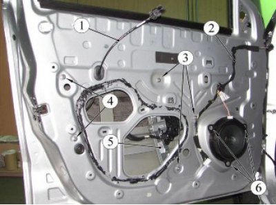
Figure 3-7 - Door fittings: 1 - cable of the inner handle of the lock drive; 2 - door wiring harness; 3 - window regulator mounting nut; 4 - nut for fastening the sliding glass guide; 5 - window lifter; 6 - loudspeaker mounting rivet
Loosen screw 4, Fig. 3-8, securing door limiter 2 to the front body pillar (torx T40 replaceable head, ratchet).
Remove the plug 3 of the limiter from the door opening (flat head screwdriver).
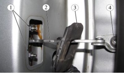
Figure 3-8 - Fastening the door opening limiter: 1 - nut for fastening the door opening limiter to the door; 2 - door opening limiter; 3 - limiter plug; 4 - screw for fastening the door opening limiter to the front body pillar
Loosen nuts 1 securing the door stop to the door panel, remove the stop (replacement head 10, ratchet).
Release the clamps 1, Fig. 3-9, of the lever 2 of the switch 8 of the front door lock and remove the lever from the switch shaft (flat head screwdriver).
Loosen screws 7 securing lock 4 to the door, remove the lock from the door cavity together with rod 3 of the lock switch and cable of the inner handle of the lock, disconnect cable of mechanism 5 of the outer handle from the lock (torx T30 replaceable head, ratchet).
Remove plug 6 from the hole in the end of the door and through the opened hole unscrew the lock switch fixing screw, remove the switch (flat screwdriver, replaceable Torx T20 head, ratchet, extension).
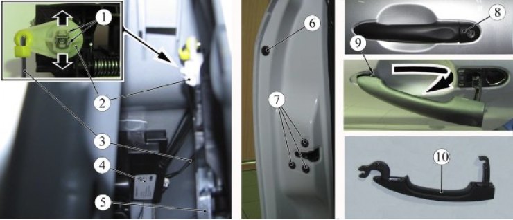
Figure 3-9 - Front door lock and its drive: 1 - lock switch lever clamps; 2 - lock switch lever; 3 - Front door lock switch rod; 4 - front door lock; 5 - mechanism of the handle of the outer lock of the front door; 6 - plug; 7 - lock mounting screws; 8 - Front door lock switch; 9 - rivet for fastening the outer handle mechanism to the door panel; 10 - outer door lock handle
To dismantle the handle 10 of the outer door lock, it is necessary to take hold of the handle and, without pulling it, move it back, then, in the moved position, pull the rear part of the handle until the rear hook comes out of the hole in the door panel and, pulling the handle with a force that overcomes the force of the hinge lock of the front part of the handle, remove the handle.
Remove the mechanism 5 of the outer handle, carefully drilling out the rivet 9 that secures the mechanism to the door panel without damaging the paintwork (drill, drill 05 mm).
Assemble the door units and parts in the reverse order of disassembly, while:
- lubricate the rubbing parts of the window lifter, sliding surfaces in the door lock, door opening limiter, rod joints and hinges (grease type TSIA-TIM-201, consumption rate - 5 g);
- when installing the external handle, ensure that the return mechanism lever is captured by the handle hook, as shown in Figure 3-10;
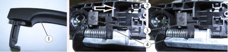
Figure 3-10 - Installing the outer door lock drive handle: 1 - outer door lock handle; 2 - outer handle return mechanism housing; 3 - hook of the outer handle; 4 - lever of the return mechanism of the outer door lock handle
- before installing the door trim, temporarily connect the window lift switch unit, the negative terminal to the battery, check and, if necessary, adjust the operation of the door lock and window lift; raise the window, disconnect the negative terminal from the battery and remove the switch unit.
The door fittings and components must be secured to all attachment points provided by the design.
When installing the housing of the return mechanism of the external handle and the loudspeaker, it is permissible to use alternative fasteners of the appropriate diameter.
Present the vehicle to the Quality Control Department. The Quality Control Department will check the vehicle for compliance with the following requirements: the doors of the body must open and close easily, spontaneous opening of the doors is not allowed; when the door locks are locked, the latter should not be opened by the outside handles; window lift mechanisms must ensure uniform, jam-free, full reversible movement of the vehicle's lowering windows.