



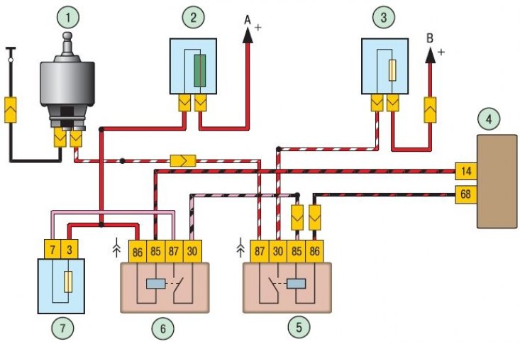
Figure 10.10. Circuit diagram for connecting the electric motor of the cooling system fan: 1 – fan electric motor; 2 – main fuse box (F1); 3 – mounting block (F1); 4 – Engine management system ECU; 5 - switch on the fan motor; 6 – Engine management system fuse box (main relay – K1); 7 – Engine management system fuse box (F1); A – to the positive terminal of the battery; B – to the main fuse box (F2)
The connection diagram of the cooling system fan electric motor is shown in the figure 10.10.